
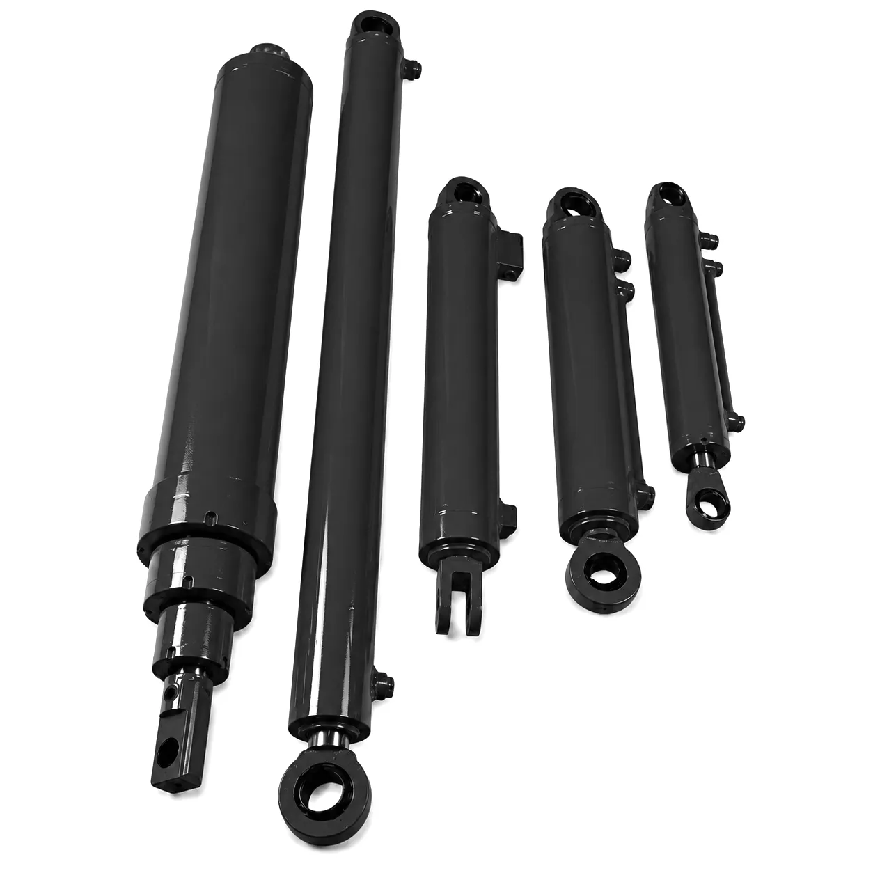
 A hydraulic boom cylinder is one of the most mechanically demanding components operating on any piece of heavy plant equipment in the United Kingdom. Whether it is lifting the articulated arm of a crane on a Birmingham infrastructure contract, extending the reach of an excavator in a Sheffield steelworks yard, or driving the dipper on a civil earthworks project in Leeds, the hydraulic boom cylinder absorbs enormous cyclic loads, lateral shock, and continuous fluid pressure — often without the maintenance attention its function demands. When a hydraulic boom cylinder begins to fail, the consequences cascade quickly: from slow hydraulic drift and unexpected pressure drops to catastrophic seal blowout and irreparable barrel scoring that renders the entire cylinder unserviceable.
Why Regular Hydraulic Boom Cylinder Inspection Is Non-Negotiable on UK Construction Sites
A single unplanned hydraulic boom cylinder failure on a UK infrastructure contract can cost between £8,000 and £25,000 per day in combined plant hire, labour standing time, and contract penalty clauses. The Health and Safety Executive’s plant maintenance guidance explicitly identifies hydraulic cylinder failure as a leading cause of serious lifting incidents. Preventive inspection is not discretionary — it is both a commercial and a statutory obligation for site operators.
The failure sequence in a hydraulic boom cylinder is almost always progressive: contaminated fluid causes microscopic rod scoring, which then accelerates seal lip wear, which introduces particle-laden fluid into the barrel, which degrades the bore surface further. By the time visible external leakage is apparent, multiple wear modes have already been active for hundreds of operating hours. Inspection at the early stage of this chain is the only intervention that is both economically viable and technically reversible without a full cylinder rebuild.
Under LOLER 1998 (Lifting Operations and Lifting Equipment Regulations), all hydraulic cylinders forming part of a lifting arrangement — including boom cylinders on cranes, telehandlers, and mobile elevating work platforms — must be subject to thorough examination at defined intervals by a competent person. Documented inspection records demonstrating cylinder condition form a core part of that examination. UK plant owners who cannot produce evidence of structured hydraulic boom cylinder inspection are exposed to significant enforcement risk under the Provision and Use of Work Equipment Regulations (PUWER) framework as well.
Working Principle and Core Material Composition of the Hydraulic Boom Cylinder
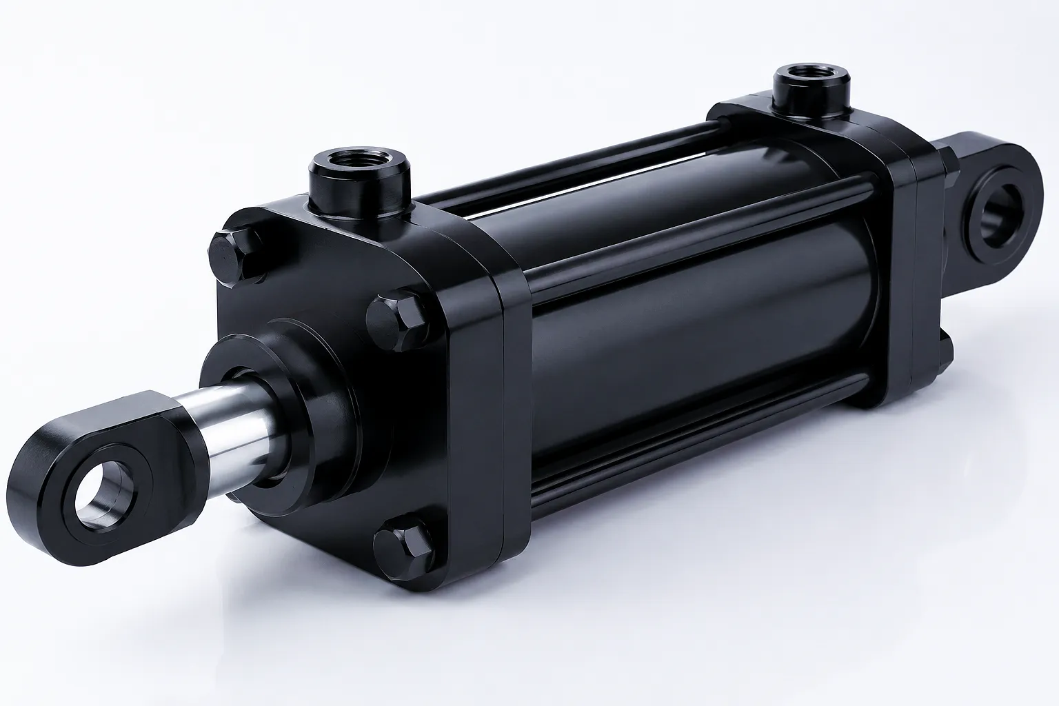
At its mechanical core, a hydraulic boom cylinder converts pressurised hydraulic fluid into controlled linear motion through the interaction of pressurised oil acting against a differential piston area. In a double-acting configuration — by far the most common arrangement in crane and excavator boom circuits — hydraulic fluid delivered to the cap end pushes the piston and rod assembly outward (extending the boom), while fluid delivered to the rod end retracts the assembly and draws the boom inward. Pressure is generated by the machine’s hydraulic pump, transmitted via control valve circuitry, and sealed within the cylinder body by a cascade of precision-machined sealing interfaces. The mechanical efficiency of this conversion is typically between 95% and 98% on a new cylinder; when that figure drops below 90%, internal bypass across worn piston seals has become significant enough to demand immediate intervention.
The material specification of a heavy-duty hydraulic boom cylinder is engineered around the simultaneous demands of high compressive strength, corrosion resistance, surface hardness at the rod, and machinability at the barrel. The cylinder barrel is typically manufactured from high-strength seamless steel tubing — cold-drawn and honed to an internal surface roughness of Ra 0.4 µm or finer — which provides both the pressure containment required at operating pressures of 250 to 350 bar and the geometric precision needed for reliable long-term seal function. The piston rod is manufactured from high-tensile carbon steel or alloy steel (commonly 42CrMo4 or equivalent EN grade), ground to h6 or h8 tolerance and then hard chrome plated to a minimum depth of 25 µm, providing a surface hardness exceeding 850 HV that resists abrasive wear from airborne particulate and dirt ingress around the rod seal interface.
End caps and gland nuts are typically machined from forged or cast ductile iron, or mild steel plate, with thread forms cut to DIN or BSP standards. Seal packages are compound assemblies combining a primary PTFE-loaded polyurethane wiper, a main rod seal in nitrile or fluorocarbon elastomer, a backup ring, and a buffer seal — each component selected for its specific resistance to the operating fluid chemistry, temperature cycle, and pressure envelope of the application. In UK market hydraulic boom cylinders operating in mineral oil circuits, NBR (nitrile butadiene rubber) is the standard elastomer; where biodegradable hydraulic fluid mandates apply — as they increasingly do under UK environmental permit conditions on sensitive civil engineering sites — EPDM or FKM (Viton) compounds are specified instead.
The 8-Point Field Inspection Protocol for Hydraulic Boom Cylinder Wear, Scoring and Seal Failure
Execute this protocol with the machine on level ground, boom fully lowered, system depressurised, and isolation valves closed. Ensure written PTW (Permit to Work) is in place.
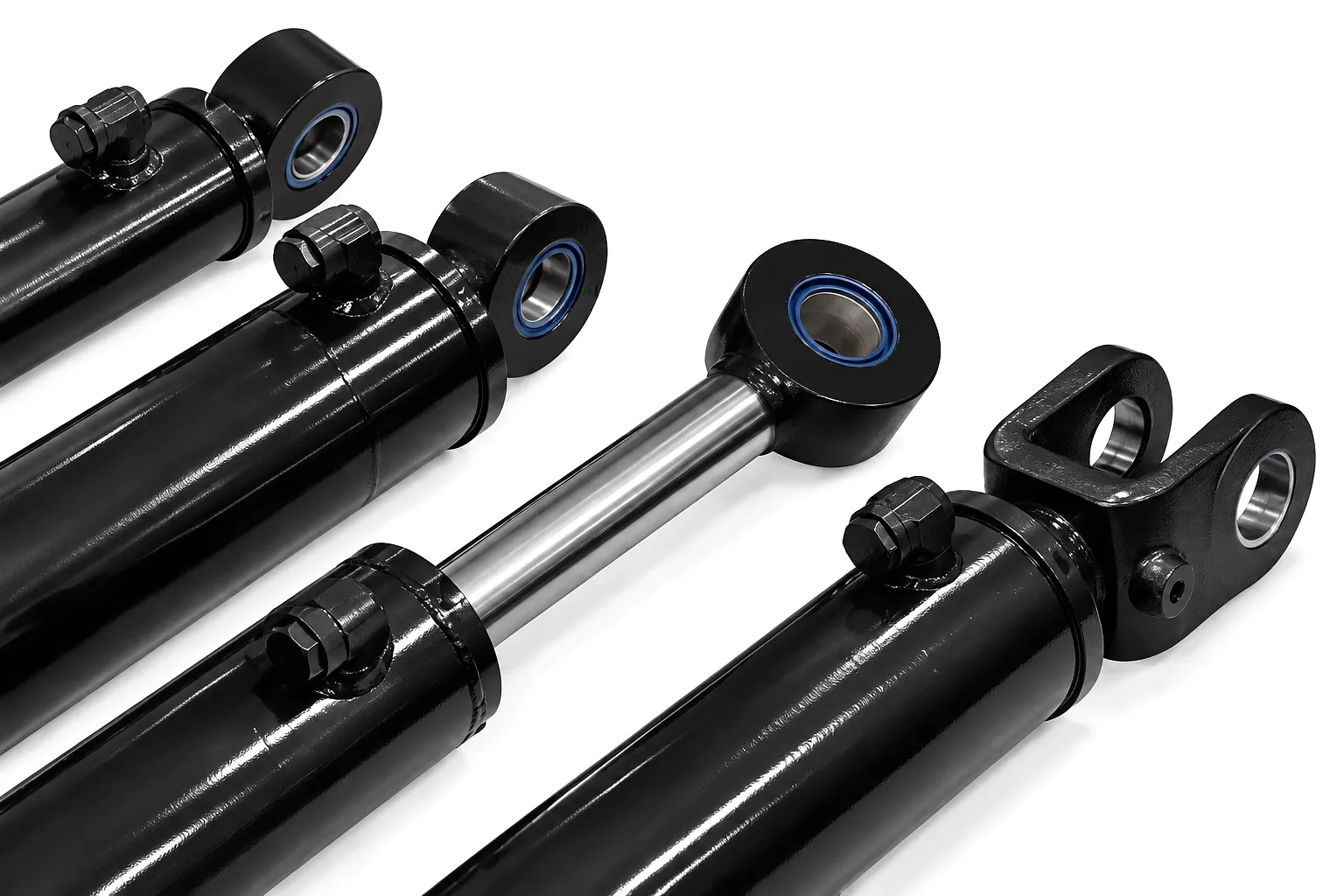
Begin with the piston rod — the highest-wear component in any hydraulic boom cylinder in field service. With the boom extended to expose the maximum possible rod length, wipe the entire exposed rod surface clean with a lint-free cloth dampened with clean hydraulic fluid. Then work along the rod length under direct light, examining for scoring marks — these appear as linear scratches or grooves running parallel to the rod axis. Light surface scoring (depth below 0.05 mm, width below 0.5 mm) can often be polished out using a fine wet-and-dry abrasive strip and will not cause immediate seal failure. Medium scoring (0.05 to 0.15 mm depth) will accelerate rod seal wear significantly and warrants cylinder removal for professional assessment. Deep scoring (over 0.15 mm, visible catch on a fingernail) is a mandatory replacement trigger — the chrome layer has been breached, base metal is exposed to corrosion, and the seal package will fail within a short service period.
Pitting — small circular or ovoid depressions in the chrome surface — indicates corrosive attack, often from condensation water in the hydraulic fluid or from aggressive groundwater contact at the rod seal during extended outdoor storage. Any pitting should be logged, photographed, and measured with a pit gauge or depth micrometer. Chrome delamination, visible as raised flakes or areas where the chrome layer has separated from the substrate, is an immediate service-out criterion with no conditional clause.
The gland assembly at the cylinder head is where the rod exits the barrel, and it houses the critical sealing stack that prevents hydraulic fluid loss and contamination ingress simultaneously. Inspect the gland face and the rod surface immediately adjacent to it. A dry gland face with a very thin film of hydraulic fluid on the rod surface is correct — this is the designed lubrication film that seals are intended to permit. Wetness beyond a thin film, any weeping droplet formation, or staining of the cylinder body below the gland all indicate progressive rod seal wear that has crossed from acceptable lubrication into active leakage.
The external wiper seal is the first line of defence against dirt ingress and is usually the first seal to show visible deterioration. Inspect the wiper lip if accessible — on many hydraulic boom cylinder designs the wiper is externally retained and can be examined without disassembly. Look for lip cracking, hardening, or deformation that indicates heat cycling damage or incompatibility with the system fluid. A wiper seal that has begun to fragment will be depositing rubber particles into the fluid circuit — a contamination source that accelerates wear at every downstream sealing surface in the system.
Internal barrel inspection requires the cylinder to be removed from the machine and disassembled — a process that should only be conducted in a clean-room workshop environment with all hydraulic ports immediately sealed on removal to prevent contamination ingress. Once disassembled, inspect the bore using a calibrated bore gauge and a high-intensity bore light. The honed bore surface should appear uniformly grey-silver with a fine cross-hatch pattern visible at close inspection. Any discolouration, rust staining, or loss of the cross-hatch pattern indicates surface degradation that will compromise piston seal function. Measure bore diameter at a minimum of three axial positions and two perpendicular radial orientations at each position to quantify ovality and barrel wear.
Barrel scoring — typically caused by hard particle contamination bypassing the filter circuit and being dragged across the bore surface by the piston — appears as longitudinal scratch marks in the bore. Even shallow bore scoring is more critical than equivalent rod scoring because it disrupts the sealing geometry of the piston seal across its entire circumference rather than at a single point. Bore scoring of any depth beyond Ra 1.6 µm at the affected zone is a mandatory re-hone or replacement trigger. In practice, a bore that requires re-honing to clean up scoring will have reduced to a diameter that demands an oversized piston seal package — a repair that represents the upper economic threshold for cylinder salvage versus replacement.
Internal leakage across the piston seal — where high-pressure fluid from one side of the piston bypasses to the low-pressure side — is the most insidious failure mode in a hydraulic boom cylinder because it produces no visible external symptom. The machine operator will notice only that the boom drifts slowly downward under load, or that extension speed and force have reduced without any apparent external leak. A cylinder drift test is the standard field diagnosis: with the system pressurised, the boom raised to a defined angle, and all control inputs locked, measure boom position drift over a timed five-minute interval. Any vertical drift exceeding the OEM specification (typically 5 to 10 mm per minute at rated load) constitutes evidence of significant piston seal bypass.
For quantified internal leakage measurement, connect a calibrated flow meter to the return port with the cylinder pressurised at rated working pressure and the rod end port connected to tank. Flow through the meter represents bypass across the piston seal assembly. On a cylinder of 100 mm bore diameter operating at 250 bar, acceptable bypass is typically below 2 cm3/min; values above 15 cm3/min indicate a piston seal package that has reached end-of-life. This test must be conducted with the cylinder oil at normal operating temperature (around 45 to 55 degrees Celsius), as cold fluid viscosity will artificially suppress leakage measurement and give a falsely optimistic reading.
Inspect the cylinder mounting interfaces — both the cap-end trunnion or eye and the rod-end clevis or bearing — for pin wear, bronze bush clearance, and crack initiation at weld toes. Pin-to-bush clearance exceeding 0.5 mm introduces lateral loading into the cylinder that accelerates rod seal and gland wear exponentially. Penetrant inspection at weld attachment points should be conducted annually on cylinders in high-cycle crane applications in Sheffield heavy industry and similar demanding environments.
Inspect all hydraulic port connections for thread damage, O-ring face seal (ORFS) condition, and evidence of seepage at the connection interface. Weeping at port connections in a hydraulic boom cylinder is often misattributed to cylinder body leakage — trace the origin carefully before condemning the cylinder assembly. BSP threaded ports should be inspected for thread deformation caused by overtightening, and all steel fittings checked for corrosion pitting, which is accelerated in the salt-laden coastal atmospheres encountered in offshore support and port infrastructure applications across UK coastal locations including Bristol, Hull, and Portsmouth.
A hydraulic oil sample taken directly from the circuit serving the boom cylinder and submitted for laboratory particle count and water content analysis is one of the most cost-effective diagnostic tools available. ISO 4406 cleanliness codes above 20/18/15 in a cylinder circuit indicate contamination levels that will rapidly accelerate all wear modes. Water content above 0.1% indicates emulsification that will degrade elastomeric seals. Many UK hydraulic service laboratories offer 48-hour turnaround analysis with full ISO reporting, providing quantified baseline data that supports scheduled maintenance decision-making with documented evidence.
After seal replacement or rod reconditioning, a full pressure test to 1.5 times maximum working pressure (MWP) — held for a minimum of 10 minutes — is mandatory before return to service. The cylinder should complete at least five full stroke cycles at operating pressure before the static hold test, to fully seat all new seals. Stroke length should be verified against the drawing tolerance, as barrel deformation or rod bending caused by side-loading events can produce an effective stroke reduction that reduces boom reach and may indicate structural damage requiring further NDT assessment before the hydraulic boom cylinder is reinstalled.
Hydraulic Boom Cylinder — Technical and Performance Specification Reference Table
| Parameter | Light Duty | Medium Duty | Heavy Duty | Inspection Threshold |
|---|---|---|---|---|
| Bore Diameter (mm) | 50 – 100 | 100 – 180 | 180 – 320 | Ovality > 0.05 mm |
| Rod Diameter (mm) | 35 – 70 | 70 – 120 | 120 – 220 | Scoring depth > 0.15 mm |
| Working Pressure (bar) | 160 – 210 | 210 – 280 | 280 – 400 | Test at 1.5× MWP |
| Chrome Plate Thickness (µm) | 20 – 30 | 25 – 40 | 35 – 60 | Replace < 15 µm residual |
| Bore Surface Roughness (Ra µm) | 0.4 | 0.4 | 0.4 | Re-hone > 1.6 µm |
| Piston Seal Bypass (cm³/min at rated P) | < 1 | < 2 | < 5 | Replace > 15 cm³/min |
| Seal Material (Mineral Oil) | NBR / PU | NBR / PU | FKM / PTFE | Replace at hardness > 90 Shore A |
| Stroke Length Range (mm) | 200 – 800 | 500 – 2,000 | 1,000 – 6,000 | Verify ± 2 mm of drawing |
| Operating Temperature Range (°C) | -20 to +70 | -30 to +80 | -40 to +100 | Sample oil at > 55°C |
| Pin-to-Bush Clearance Limit (mm) | 0.3 | 0.4 | 0.5 | Replace bush > limit |
Hydraulic Boom Cylinder Product Range
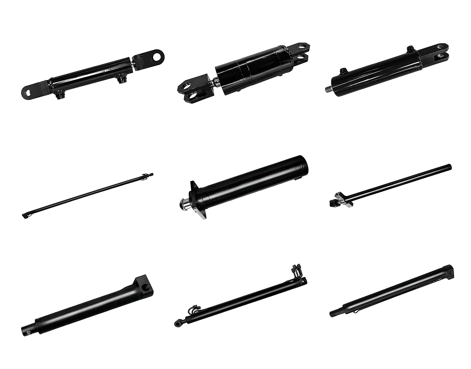
Precision-engineered for structural frame support applications — robust, high-load capacity, available in custom stroke lengths for UK plant operators.
View Product →
Designed for demanding outrigger and rack stabilisation duties — ideal for mobile crane and heavy lift applications across UK infrastructure sectors.
View Product →
Industrial Application Scenarios for Hydraulic Boom Cylinder Inspection and Maintenance
Birmingham’s ongoing infrastructure investment — including HS2 enabling works, the city’s expanding urban regeneration zones, and major commercial development schemes — places crane-mounted hydraulic boom cylinders in continuous high-intensity service. At these sites, boom cylinders are operating at or near their duty cycle maximums, often in tight urban confines where a cylinder drift event or gland leak creates an immediate safety exclusion zone with serious programme consequences. Scheduled inspection protocols applying the drift test, rod surface check, and oil analysis described in this guide are now being incorporated into plant management contracts across Birmingham’s major civil engineering programmes.
Sheffield’s surviving heavy steel manufacturing and specialist fabrication sector operates hydraulic boom cylinders in some of the most thermally aggressive environments in UK industry. Cylinders on ladle cranes, manipulator arms, and press-loading equipment are exposed to radiant heat from molten metal operations that can elevate ambient temperature around the cylinder gland well beyond normal operating limits. This thermal stress accelerates elastomeric seal hardening and cross-linking — a phenomenon inspectors should look for as gland seal lip cracking even at low operating hours. FKM (Viton) seal compounds and synthetic hydraulic fluids with high thermal stability are the correct specification for this application, and cylinder inspection intervals in Sheffield heavy fabrication environments should be reduced from the standard annual to quarterly.
Marine construction and offshore wind installation activities — increasingly active across UK east coast locations from Aberdeen down through Hull to Great Yarmouth — expose hydraulic boom cylinders to salt spray, high humidity, and intermittent immersion conditions that create the most aggressive corrosion environments in UK industry. Chrome rod pitting, which in an inland construction environment might develop over years, can initiate within months of marine deployment without appropriate surface protection and inspection regimes. Inspection for these applications should incorporate a torque check on all gland retaining nuts (salt corrosion attacks thread interfaces), ultrasonic wall thickness measurement on the barrel body, and a visual check for biofouling growth around port fittings that can mask early-stage seepage.
Tunnel boring machine (TBM) auxiliaries, rail maintenance plant, and underground civil machinery operating in the confined spaces of UK rail and metro infrastructure projects face a unique boom cylinder inspection challenge: access is severely limited, service windows are short (often restricted to weekend engineering possessions), and any fluid loss inside a tunnel creates environmental contamination and fire-risk issues that trigger immediate environmental incident reporting procedures. For these applications, the hydraulic boom cylinder inspection protocol should include an accelerated leak-check procedure using fluorescent dye tracer added to the hydraulic circuit, allowing UV lamp detection of even micro-weeps at gland, port, and body weld interfaces without the machine needing to be extracted from the tunnel environment for full disassembly.
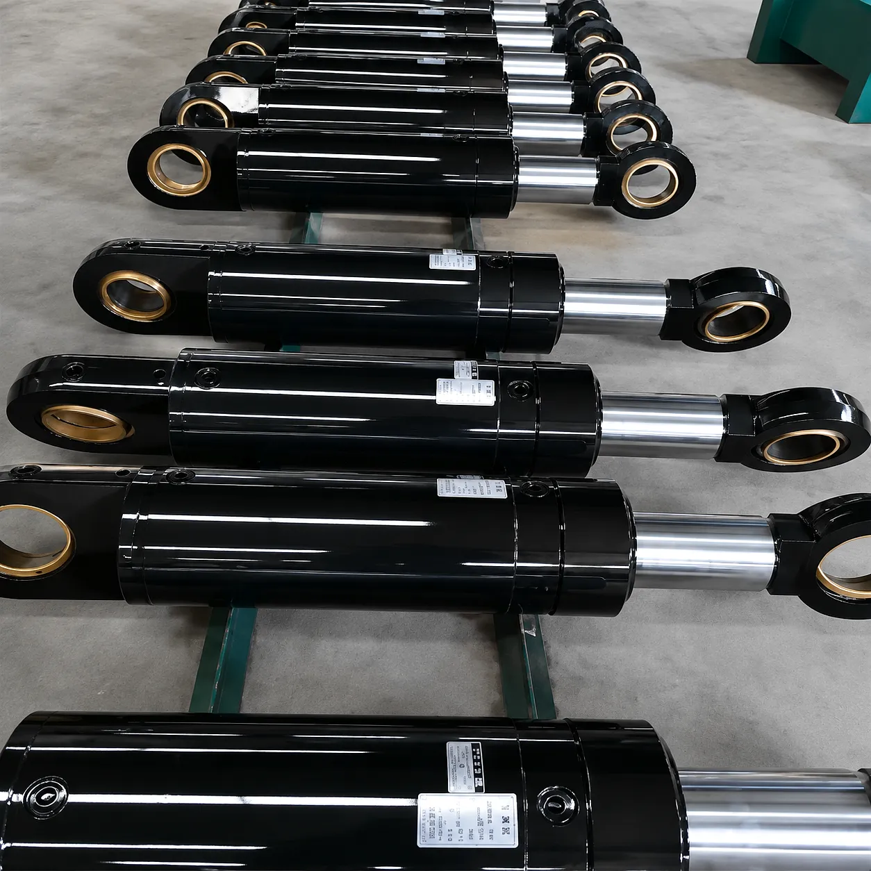 Ever Power’s hydraulic boom cylinder manufacturing operation is built around the principle that supply chain reliability and engineering customisation are not competing demands — they are complementary capabilities that define a world-class cylinder supplier. Our production facility operates precision CNC honing machines, deep-hole boring centres, and hard-chrome plating lines that are calibrated to tolerances meeting or exceeding the most demanding OEM specifications in the global crane and heavy plant sector. Every hydraulic boom cylinder leaving our facility has been pressure-tested to 1.5 times MWP, dimensionally verified against a full inspection report, and issued with a material certificate traceable to the original steel heat batch.
Customer Success: Leeds Heavy Lift Contractor — Boom Cylinder Replacement Programme
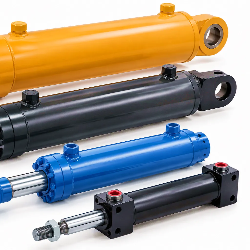 A specialist heavy lift and crane hire contractor based in Leeds, operating a fleet of 14 lattice-boom crawler cranes on major industrial and infrastructure contracts across West Yorkshire and the East Midlands, approached Ever Power in the autumn of 2024 following a series of boom cylinder serviceability issues that had resulted in three separate machine groundings within a six-month period. Two of the affected cylinders had developed piston seal bypass to the point where measurable boom drift under rated load had triggered a mandatory stop-and-inspect order from the site LOLER competent examiner. The third cylinder had suffered catastrophic rod seal failure during a precision lift, releasing approximately 40 litres of hydraulic oil and triggering an environmental incident report with the site’s Environment Agency permit holder.
Working closely with the contractor’s plant manager and their in-house maintenance engineer, Ever Power conducted a full dimensional survey of the existing cylinder population — mapping bore diameters, rod diameters, port configurations, stroke lengths, and mounting interface dimensions across all 14 machines. Of the total boom cylinder inventory, nine cylinders were identified as candidates for direct OEM-equivalent replacement, and four required engineered substitute designs that incorporated updated seal packages using FKM compounds and improved wiper seal geometry to address the recurring contamination ingress mode that had been identified as the root cause of the failure sequence. The fourteenth machine received a cylinder with an integrated stroke-end cushioning circuit, addressing a specific shock-loading pattern that had been noted in the operational data as a contributor to premature rod scoring on that particular crane’s duty cycle.
Ever Power delivered the complete replacement cylinder programme — thirteen units across the first delivery tranche, with the bespoke cushioned cylinder following four weeks later — with DDP logistics to the contractor’s Leeds maintenance depot. The entire cylinder inventory was changed out during a planned two-week maintenance shutdown, with full LOLER-compliant pressure test certificates and dimensional inspection documentation supplied for each unit. In the twelve months following the programme completion, the contractor reported zero unplanned boom cylinder failures across all 14 machines and a documented reduction in hydraulic fluid consumption of approximately 380 litres per year across the fleet — a direct measure of the elimination of chronic gland and piston seal leakage that had been accepted as normal operating loss before the Ever Power replacement programme.
“We’ve used Ever Power’s hydraulic boom cylinders across our crane fleet in Leeds and the surrounding region for over a year now, and the improvement in seal longevity compared to our previous supplier is genuinely striking. The FKM seal package they recommended for our high-cycle cranes has made it through 18 months of continuous service without a single gland leak — previously we were seeing rod seal weeping within eight months on the same machines.”
“The dimensional survey that Ever Power’s engineering team carried out on our existing cylinder inventory was genuinely impressive — they identified a non-standard bore tolerance on two of our older machines that our previous suppliers had simply ignored and replaced like-for-like. The corrected design they supplied has eliminated the internal bypass issue that had been causing boom drift on those two cranes. That level of technical attention to a replacement programme is rare from any supplier, and certainly not what we expected at this price point.”
“We operate tunnel support and lining equipment in confined environments for a major rail contractor across the north of England, and finding a hydraulic boom cylinder supplier who understands the environmental and logistical constraints of underground operations has been a persistent challenge. Ever Power’s DDP delivery to our site compound, plus the full pressure-test certificates provided for every cylinder, made our LOLER documentation process straightforward. The cylinders themselves have performed without issue across 14 months of underground operation.”
Ever Power’s engineering team serves UK plant operators, crane contractors, and OEM integrators with precision-manufactured hydraulic boom cylinders, fast DDP delivery, and full LOLER documentation support.
Get a Quote — [email protected]
 English
  Italian
  Portuguese
  Dutch
Dutch  Swedish
  Danish
  Finnish
  Polish
  Hindi
Hindi  Kazakh
  Turkish
  Ukrainian
  Romanian
  Spanish
  German
  Russian
  Korean
  Japanese
  Vietnamese
  Thai
Thai  Indonesian
  Malay
Malay  French
  Greek
Greek