
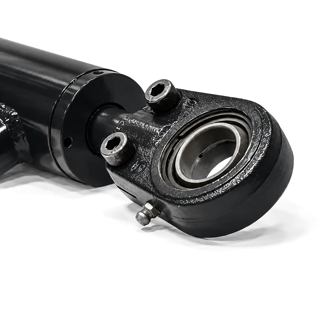
 Hydraulic cylinder creep is one of those problems that starts quietly — a press ram that drifts a few millimetres overnight, a clamp that slowly loses its grip mid-shift, an excavator arm that sinks when the operator releases the controls. In the UK’s precision manufacturing sector, especially in hubs like Birmingham’s automotive supply chain and Sheffield’s steel processing facilities, even a two-millimetre drift can result in scrap batches, safety incidents, and unplanned downtime costing thousands of pounds per hour. The frustration is compounded by how difficult creep can be to isolate: the symptom appears gradually, the system still pressurises correctly, and the root cause may lie deep within the cylinder assembly, the valve block, or even the hydraulic fluid specification.
This guide breaks down exactly what hydraulic cylinder creep is, why it happens, and — critically — how to prevent it from recurring. Whether you manage a fleet of heavy-duty welded cylinders in an off-highway application or specify tie-rod units for production presses in the East Midlands, understanding creep at a mechanical level will save your team significant maintenance hours and protect your production targets. The information here draws on genuine field diagnostics and reflects the real-world conditions faced by UK hydraulic engineers across agriculture, construction, food processing, and heavy manufacturing.
Get a Free Quote from Ever Power →
Response within 24 hours · UK-compatible specifications · Custom engineering available
What Exactly Is Hydraulic Cylinder Creep?
Hydraulic cylinder creep — sometimes called cylinder drift — is the slow, unintended movement of the piston rod when the hydraulic system is nominally at rest with the control valve in the neutral or hold position. Unlike sudden pressure loss or a burst seal, creep unfolds incrementally. A hydraulic cylinder with a creep fault may drop its load by only a fraction of a millimetre per minute, but over an eight-hour shift that fraction compounds into a serious positional error.
The distinction between creep and collapse is important. Collapse implies a catastrophic seal failure or a burst line where the cylinder rapidly retracts or extends under load. Creep, by contrast, is a controlled but unwanted movement driven by small but persistent leakage — either internal (past the piston seals) or external (past the rod seal and gland). Both types of leakage can coexist, and both contribute to the net drift rate that an engineer observes at the actuator tip.
The Seven Root Causes of Hydraulic Cylinder Creep
The piston seal is the primary barrier separating the extend and retract chambers inside the cylinder barrel. When this seal wears — typically through abrasive particles in the hydraulic fluid, incorrect seal compound selection, or prolonged operation at temperatures exceeding the seal’s rated limit — hydraulic oil migrates across the piston, equalising pressure on both sides. The result is a cylinder that can no longer hold position under load. In tie-rod cylinders commonly used in UK industrial presses, polyurethane piston seals operating at pressures above 250 bar accelerate wear dramatically if the fluid viscosity grade is mismatched to the ambient temperature range typical in northern England’s unheated workshops.
Even when a cylinder’s own seals are in perfect condition, creep can originate in the directional control valve. Spool-type valves — the dominant design in UK mobile plant and industrial machinery — develop internal leakage as their spool-to-bore clearances increase with wear. When the valve is centred (neutral), oil should be blocked from both cylinder ports; a worn spool allows a small continuous bypass flow that, over time, creates a net pressure differential across the piston. Identifying valve-induced creep requires isolating the cylinder from the valve block and testing hold pressure directly — a step many maintenance teams skip during fault-finding, leading to unnecessary cylinder replacements.
Counterbalance valves (CBVs) are specifically designed to prevent load-induced creep in suspended-load applications such as crane outriggers, agricultural loader arms, and rubbish-truck lifting mechanisms common across UK waste management fleets. When a CBV is set too low relative to the maximum load-induced pressure, it cracks open slightly under static load and allows controlled oil escape. When set too high, it creates pressure spikes during controlled lowering. Regular recalibration — typically to 1.3× the maximum load-induced pressure — is essential and is frequently overlooked during scheduled service intervals in favour of more visible maintenance tasks.
Hydraulic fluid contamination — whether from water ingress (particularly prevalent in outdoor UK agricultural applications during wet seasons), metallic swarf from cylinder bore scoring, or degraded fluid that has lost its anti-wear additives — accelerates seal degradation and abrades valve spools far faster than clean fluid. ISO cleanliness level 16/14/11 or better is widely recommended for mobile hydraulics, yet field samples routinely show UK plant operating at 19/17/14 or worse. A contamination-driven creep fault is self-reinforcing: particle damage creates more particles, and the cylinder that starts with mild creep rapidly progresses to significant drift without intervention.
The cylinder barrel bore must maintain a precise honed surface finish — typically Ra 0.2–0.4 µm for dynamic sealing — to ensure the piston seal maintains consistent contact and radial load. When the bore scores due to side-loading (common in boom cylinders on excavators and forestry equipment operating on uneven UK terrain), the sealing surface becomes irregular. Even a freshly replaced seal cannot prevent bypass flow past a scored bore. Deep scoring also encourages localised pressure concentrations that accelerate fatigue cracking along the barrel wall, converting a creep fault into a structural risk that may require full barrel replacement or cylinder exchange.
When a hydraulic cylinder warms during continuous operation, the trapped fluid volume in a sealed chamber expands. In a correctly functioning cylinder this creates a slight pressure rise that is then relieved through the relief valve or absorbed by circuit compliance. In a cylinder with marginal sealing, the thermal pressure spike drives additional bypass, pushing the rod further out or in. This thermally-driven creep is particularly noticeable in the first 30 minutes of operation during cold UK mornings, when the differential between ambient temperature and operating temperature is greatest — a diagnostic clue that maintenance engineers should note carefully.
Seal selection is rarely given the engineering attention it deserves during cylinder sourcing, yet material specification is one of the most influential factors in long-term creep resistance. Nitrile rubber (NBR) seals are widely used as a low-cost default, but they degrade rapidly when exposed to fire-resistant phosphate ester fluids common in steel mills and foundries across Sheffield and the Black Country. Fluoroelastomer (FKM) or polytetrafluoroethylene (PTFE) seals offer far superior chemical resistance and lower compression set — meaning they maintain their radial preload over time rather than relaxing and allowing bypass. Specifying the wrong seal compound for your fluid and temperature range is one of the most common causes of premature hydraulic cylinder creep in the UK manufacturing sector.
Hydraulic Cylinder Creep: Diagnostic & Performance Reference Table
| Fault Type | Typical Symptom | Diagnostic Test | Typical Drift Rate | Recommended Fix |
|---|---|---|---|---|
| Piston Seal Bypass | Load-induced rod retraction under sustained hold | Isolate valve, pressurise cap-end, measure drift | 5–15 mm/hr | Reseal with OEM-spec piston seal kit |
| Rod Seal Leak | Visible oil film on rod; system pressure slowly falls | Visual inspection; measure oil loss per cycle | 2–8 mm/hr | Replace rod seal; inspect rod surface finish |
| Control Valve Spool Wear | Both extend & retract drift; worse with multiple cylinders | Dead-end pressure test at cylinder ports | Variable, 2–10 mm/hr | Rebuild or replace valve spool assembly |
| CBV Miscalibration | Drift under suspended load only; normal on flat | Check CBV cracking pressure vs load pressure | 1–5 mm/hr | Recalibrate to 1.3× max load pressure |
| Bore Scoring | Creep that worsens despite fresh seals | Borescope bore inspection; measure ovality | Highly variable | Re-hone or replace barrel; full rebuild |
| Fluid Contamination | Progressive worsening across multiple cylinders | ISO cleanliness particle count analysis | Accelerating over weeks | Flush system; replace fluid; fit high-efficiency filtration |
Seal Materials: Choosing Right to Prevent Creep
Selecting the appropriate seal compound is arguably the single highest-leverage decision in hydraulic cylinder specification. The wrong material in the wrong application produces the ideal conditions for early creep onset, regardless of how well the rest of the cylinder is engineered. The following breakdown reflects the material landscape across the hydraulic cylinders supplied to UK industry, covering operating conditions from coastal offshore platforms in Aberdeen to high-temperature steel processing lines in Rotherham.
A Structured Diagnostic Protocol for Hydraulic Cylinder Creep
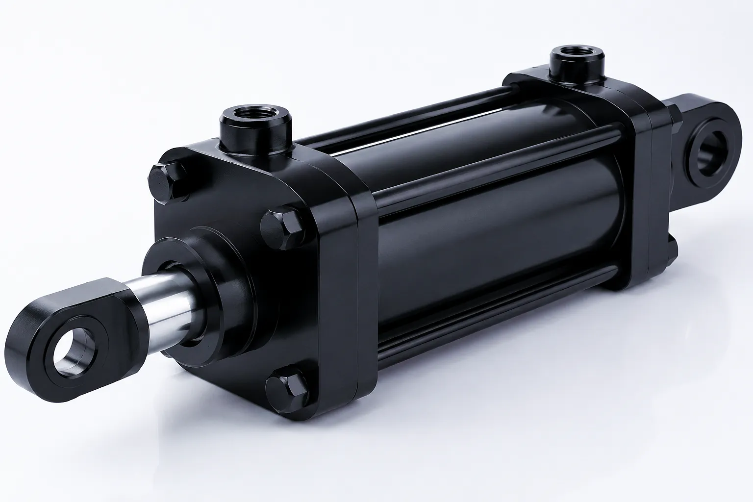 A systematic approach to diagnosing hydraulic cylinder creep saves significant time compared to the common trial-and-error method of replacing seals and hoping the problem resolves. The structured protocol below has been developed from maintenance practice across UK industrial sites and reflects the logical sequence of tests that progressively isolate the fault location to either the actuator, the valve assembly, or the circuit architecture.
Begin by observing the direction and rate of drift under a known, measured load. Retraction drift under a compressive load suggests piston seal bypass or CBV malfunction. Drift that occurs identically in both directions under any load, however, tends to point toward valve spool leakage rather than the cylinder itself. Record the drift rate in millimetres per minute across at least three measurement intervals to establish whether the rate is constant (suggesting a fixed-size leak path) or accelerating (suggesting temperature effects or a seal that is progressively failing).
Isolate the cylinder from the valve block by capping the hose ports and applying a test pressure equivalent to the system’s maximum operating pressure. Observe for pressure decay over 15 minutes. Rapid decay (greater than 5% per minute) indicates significant internal or external cylinder leakage. Negligible decay indicates the cylinder is sound and the fault lies upstream in the valve or circuit logic.
Where cylinder leakage is confirmed, distinguishing internal from external requires careful observation. External leakage is visible on the rod surface or at the gland. Internal leakage (piston bypass) produces no visible oil loss but can be confirmed by simultaneously pressurising the cap-end port and measuring the flow rate returning at the rod-end port whilst it is vented to tank — any measurable return flow at rated pressure confirms internal bypass.
How to Stop Hydraulic Cylinder Creep: Prevention Strategies That Work
The most effective approach to eliminating hydraulic cylinder creep is prevention through specification — selecting components and system architecture that are inherently resistant to the conditions that cause drift in the first place. In the UK’s demanding industrial environment, where equipment may operate year-round in variable temperatures from sub-zero Scottish winters to summer peak temperatures in English factories, this means taking a climate-aware approach to seal selection, fluid specification, and cylinder design.
Load-holding valves — whether implemented as counterbalance valves in external cartridge form or pilot-operated check valves integrated directly at the cylinder port — provide a layer of mechanical protection against creep that no seal alone can replicate. A well-specified load-holding valve maintains position even if the cylinder develops modest internal leakage, giving the maintenance team time to identify and correct the underlying fault before it becomes a safety issue. For applications in Birmingham’s automotive press shops or Sheffield’s plate-rolling operations where positional accuracy is critical, these valves should be considered standard rather than optional.
- ● Specify FKM or PU seals for your fluid type
- ● Maintain ISO 16/14/11 fluid cleanliness
- ● Fit load-holding valves at cylinder ports
- ● Specify bore surface finish Ra 0.2–0.4 µm
- ● Use hard chrome or ceramic-coated rods
- ● Calibrate CBVs seasonally in temperature-variable sites
- ● Schedule annual valve spool clearance measurement
Fluid management is equally important and often underinvested. A high-performance hydraulic cylinder with correctly specified seals will develop creep prematurely if the fluid is contaminated with water or particles. Establishing a quarterly fluid analysis programme — particle count, water content, TAN (total acid number), and viscosity measurement — gives the maintenance team early warning of degradation trends before they manifest as cylinder faults. Several specialist fluid analysis laboratories operate across the UK with same-week reporting, making this a practical addition to any condition monitoring programme.
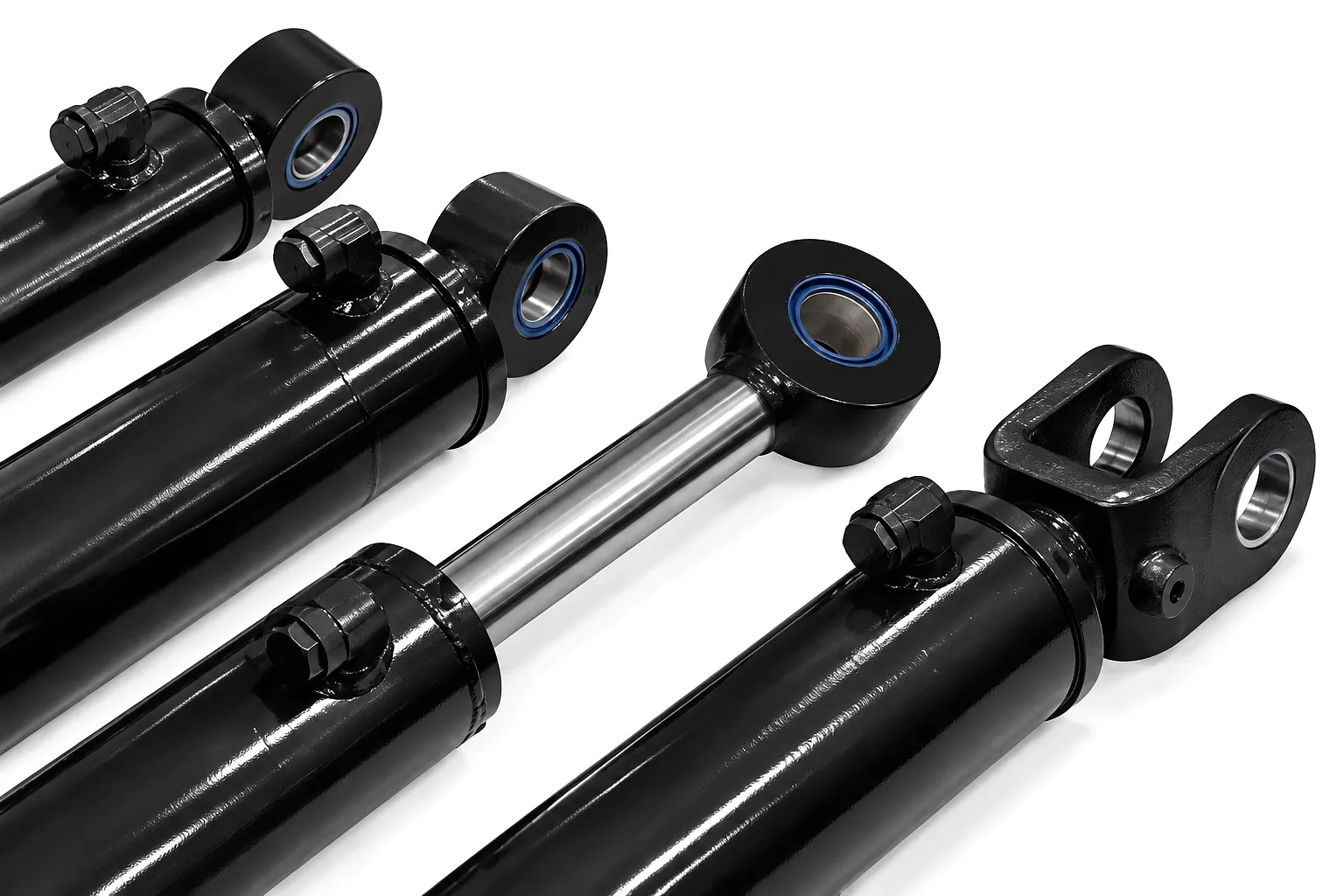
Industrial Application Scenarios Where Creep Control Is Critical
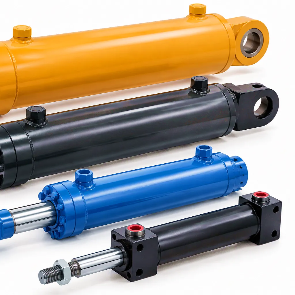
Customer Success Story: Sheffield Steel Processing — Eliminating Costly Gauge Drift
🏭 Flat Steel Processing
Problem: Cylinder Creep
A medium-sized flat steel coil processing centre based in the Lower Don Valley — supplying cut-to-length and slitting services to Sheffield’s precision engineering community — was experiencing persistent gauge variation in their hydraulic straightening line. The roller-leveller machine used 12 vertical positioning cylinders to set the levelling roller gap, and three of these were developing creep rates of 3–6 mm per hour under operating loads, causing the strip thickness output to drift beyond the ±0.05 mm tolerance band required by their automotive customers.
Their in-house maintenance team had replaced the piston seals twice in 18 months with standard catalogue NBR seal kits from a local distributor, achieving only temporary improvement before creep returned within three months of each rebuild. The cost in rejected material, rework, and customer complaints was approaching £40,000 annually — excluding the maintenance labour for the repeated seal replacements.
Ever Power’s UK technical sales team conducted an on-site assessment and identified three compounding factors: the plant used phosphate ester fire-resistant fluid incompatible with NBR seals; the bore finish on the three worst-offending cylinders had degraded beyond Ra 0.8 µm due to side-loading from strip camber; and the counterbalance valves were set 15% below the required minimum cracking pressure. Ever Power supplied replacement cylinders with FKM seal packs, re-honed bores (Ra 0.25 µm), and hard chrome rods, along with a pre-set CBV at the correct specification. Fourteen months after installation, zero creep events have been recorded, and the plant’s gauge deviation statistics show the straightening line now consistently performs within ±0.03 mm — tighter than the original specification.
What Our UK Customers Say
“We had been fighting cylinder creep on our straightening line for nearly two years. Ever Power didn’t just sell us new cylinders — they diagnosed the actual problem. The FKM seal specification combined with the correct CBV setting has completely eliminated the positional drift we had accepted as normal. The bore finish quality is noticeably superior to what we had been using.”
“We source hydraulic cylinders for our automotive press lines from multiple suppliers, but Ever Power’s application-specific approach stands out. When we specified the bore finish requirement and FKM seal pack for our phosphate ester circuit, they delivered to spec without requiring us to repeat our requirements three times. Lead time to our Birmingham facility was within the agreed window and packaging protected the chrome rod finish perfectly during transit.”
“Our offshore platform crane cylinders were replaced on a two-year cycle due to creep-related position hold failures. Ever Power supplied FKM-sealed, ceramic-coated rod cylinders with integrated port-block load-holding valves. After 26 months of North Sea service, none of those cylinders has required replacement or re-sealing. The total cost of ownership argument for specifying correctly the first time is now very clear to our operations team.”
Ever Power Hydraulic Cylinder — Technical & Performance Specification Table
| Parameter | Standard Specification | Custom / Extended Range |
|---|---|---|
| Bore Diameter | 50 mm – 320 mm | Up to 500 mm (welded series) |
| Rod Diameter | 28 mm – 220 mm | Custom per application load |
| Max Working Pressure | 250 bar | 350 bar (heavy-duty welded) |
| Stroke Length | 100 mm – 2,500 mm | Up to 4,000 mm (custom) |
| Bore Surface Finish | Ra 0.2 – 0.4 µm | Ra 0.1 µm (precision grade) |
| Rod Surface Treatment | Hard Chrome (25–30 µm) | Ceramic / HVOF / Nickel Chrome |
| Standard Seal Material | PU + NBR composite pack | FKM, PTFE, HNBR on request |
| Operating Temperature | -20°C to +120°C (NBR/PU) | -40°C to +200°C (FKM) |
| Barrel Material | E355 / ST52 seamless cold-drawn | Stainless 316L, duplex on request |
| Pressure Test Standard | 1.5× MWP, 100% end-of-line | PSSR 2000 compliance available |
| Load-Holding Valve Option | External cartridge CBV available | Port-block integrated POCV / CBV |
Frequently Asked Questions
Voice-search optimised answers for UK hydraulic engineers and buyers
Tell us your bore diameter, stroke, operating pressure, and fluid type — our engineers will specify the right seal pack and surface finish to stop creep before it starts.
UK B2B enquiries welcome · Serving Birmingham · Sheffield · Manchester · Leeds · Aberdeen
 English
  Italian
  Portuguese
  Dutch
Dutch  Swedish
  Danish
  Finnish
  Polish
  Hindi
Hindi  Kazakh
  Turkish
  Ukrainian
  Romanian
  Spanish
  German
  Russian
  Korean
  Japanese
  Vietnamese
  Thai
Thai  Indonesian
  Malay
Malay  French
  Greek
Greek