
 Across the construction sites of Birmingham, the docklands of Southampton, and the offshore wind assembly yards stretching from Aberdeen to the Humber Estuary, two crane families dominate the heaviest lifts: the crawler crane and the mobile crane. Both rely on hydraulic boom cylinders to raise, angle, and hold their booms under enormous stress. Yet the cylinders installed in each machine are far from interchangeable. Their bore diameters, stroke lengths, sealing systems, mounting geometries, and material specifications differ in ways that directly reflect the fundamentally different operational demands placed on each platform. Understanding those differences is not a matter of academic interest — it is essential knowledge for procurement engineers, maintenance supervisors, and fleet managers who need to specify the right hydraulic component, source a reliable replacement, or commission a custom cylinder that will hold its rated pressure after ten thousand hours of service in the British climate.
Why Crawler and Mobile Cranes Place Opposite Demands on Boom Cylinders
 A crawler crane is a machine built around permanence of position. It moves on steel tracks, works from a prepared pad, and is expected to perform the same high-tonnage lift cycle hundreds of times without relocating. Its boom cylinder, therefore, is engineered to deliver massive sustained thrust — often exceeding 400 bar of working pressure — across an extremely long stroke that may span several metres. The cylinder body can be heavy and large in diameter because weight is not the primary concern; structural rigidity and pressure-holding endurance are. In a Sheffield steelworks or a power station construction site in the East Midlands, a crawler crane may sit in one position for weeks, and its boom cylinder must tolerate that sustained loaded state without rod seal weep or bore surface degradation.
A mobile crane — whether a truck-mounted all-terrain unit or a rough-terrain machine moving between sites across the UK motorway network — lives a completely different hydraulic life. It must travel under strict axle load limits, often operating under the Road Vehicles (Construction and Use) Regulations 1986 and its subsequent amendments. Every kilogram of cylinder weight has a cost. The boom cylinder on a mobile crane is therefore a compromise between stroke capacity, bore diameter, and mass, executed through thinner-wall high-strength steel, telescoping multi-stage designs, and compact head configurations. Where a crawler cylinder is a single-acting or double-acting monolith, mobile crane cylinders are frequently multi-stage telescopic assemblies that extend a boom from a transport-friendly compact length to a full working radius in a matter of seconds.
Materials and Metallurgy: The Steel Grades That Separate Durability from Weight Savings
The choice of steel for a boom cylinder rod is not arbitrary. It begins with the fundamental mechanical requirement: the rod must resist column buckling under compressive hydraulic loads, maintain a surface hardness sufficient to protect the seals from abrasive particles in the surrounding atmosphere, and resist corrosion in an environment that — particularly on UK coastal and offshore sites — carries significant salt spray and humidity. For crawler crane boom cylinders, the rod material is typically EN 10277-grade high-carbon chrome steel, induction-hardened and ground to a surface roughness of Ra 0.2 µm or better, then hard-chrome plated to a minimum deposit thickness of 25 µm. This combination delivers a Vickers hardness of 850–1000 HV at the surface while maintaining the core toughness needed to absorb the shock loads that occur during sudden load application or wind gust response.
Mobile crane telescopic cylinder stages introduce a different material challenge. Each successive inner stage of a multi-stage cylinder must fit inside the previous one with tolerances tight enough to prevent excessive internal leakage, yet the wall thickness must be minimised to keep the collapsed assembly within the crane’s transport envelope. Here, manufacturers turn to seamless cold-drawn steel tubing in grades equivalent to ST 52-3 or its modern EN 10210 successors, sometimes paired with chrome-nickel alloying to allow thinner walls without sacrificing yield strength. The cylinder barrel itself — particularly for single-acting units used on mobile crane luffing systems — may be manufactured from honed hydraulic cylinder tubing with a bore tolerance of H8, allowing the piston to develop a true hydraulic seal without relying entirely on synthetic seals to compensate for bore geometry errors. This precision-honing process is a hallmark of serious cylinder manufacturing, and it is one of the quality markers that distinguishes a reliable boom cylinder from a budget substitute that will begin leaking within its first year of service.
How the Hydraulic Principle Operates Differently Across Crane Platforms
 At its core, a boom cylinder converts hydraulic pressure into linear mechanical force. Pressurised oil enters the cylinder from the hydraulic power unit — see our Custom Hydraulic Power Unit for purpose-built solutions — acts on the piston face, and pushes the rod outward. The force developed equals the hydraulic pressure multiplied by the effective piston area. In a double-acting cylinder, pressure can be applied to either side of the piston, allowing both extension and retraction under powered hydraulic load. In a single-acting cylinder, the rod is extended by hydraulic pressure and retracted by the weight of the boom structure and gravity.
Crawler crane boom systems almost exclusively use double-acting cylinders because the boom must be raised and lowered under full load control in both directions. When a crawler crane is lifting a 500-tonne load in a nuclear decommissioning site in Cumbria, the cylinder must hold that load stationary against gravity, wind, and any dynamic forces introduced by the rigging system. This requires the cylinder to be paired with a hydraulic load-holding valve — typically a pilot-operated check valve or a counterbalance valve — that prevents the rod from drifting under load even if the hydraulic pump is switched off. The sealing system in this application sees sustained high static pressure for extended periods, a regime that is far more demanding on seal compression-set resistance than cyclic dynamic pressures.
Mobile crane telescopic cylinders operate on a different principle. In a three-stage or five-stage telescopic boom, the cylinder stages extend sequentially: the outermost barrel extends first under the full system pressure, and as it reaches its stroke limit, a sequencing valve or mechanical stop redirects oil to the next inner stage. This sequential extension creates very specific pressure spike risks at each stage transition, and the cylinder seals — particularly the inter-stage wiper and pressure seals — must tolerate these transient high-pressure events thousands of times over the machine’s service life. The hydraulic circuit for a mobile crane boom is therefore substantially more complex than a crawler crane equivalent, incorporating sequence valves, flow dividers, and pilot-operated relief valves that protect individual stages from over-pressurisation during sequential deployment.
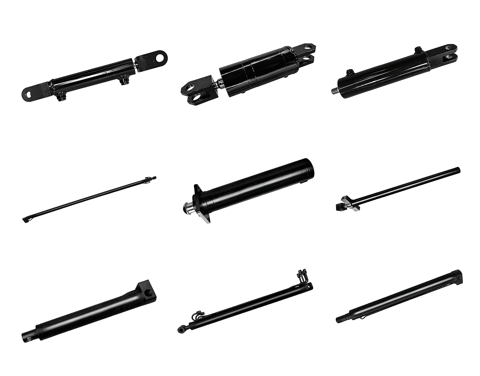
Hydraulic Rotary Actuator Steering Cylinder
Engineered for precise angular control in crane slewing and steering applications, with high-torque output and compact mounting geometry suited to both crawler and mobile platforms.
Core Design Differences: Six Engineering Dimensions That Define Each Cylinder Type
Crawler crane boom cylinders typically run single-stage strokes of 2,500–6,000 mm with bore diameters of 160–360 mm, generating thrust forces measured in the hundreds of tonnes. Mobile crane telescopic cylinders achieve comparable working extensions using three to six nested stages, each with a stroke of 1,200–2,500 mm, inside a collapsed assembly that fits within a transport height of under 4 metres.
Crawler cylinders use robust quad-ring and composite PTFE-backed seal assemblies designed for sustained static pressure up to 450 bar. Mobile crane telescopic stages require inter-stage dynamic seals — typically polyurethane U-cups with steel energisers — that tolerate both pressure and lateral bending loads as stages deflect under asymmetric boom loading. These seals are sized to UK-market hydraulic fluid specifications and must perform reliably in ambient temperatures from -15°C to +50°C.
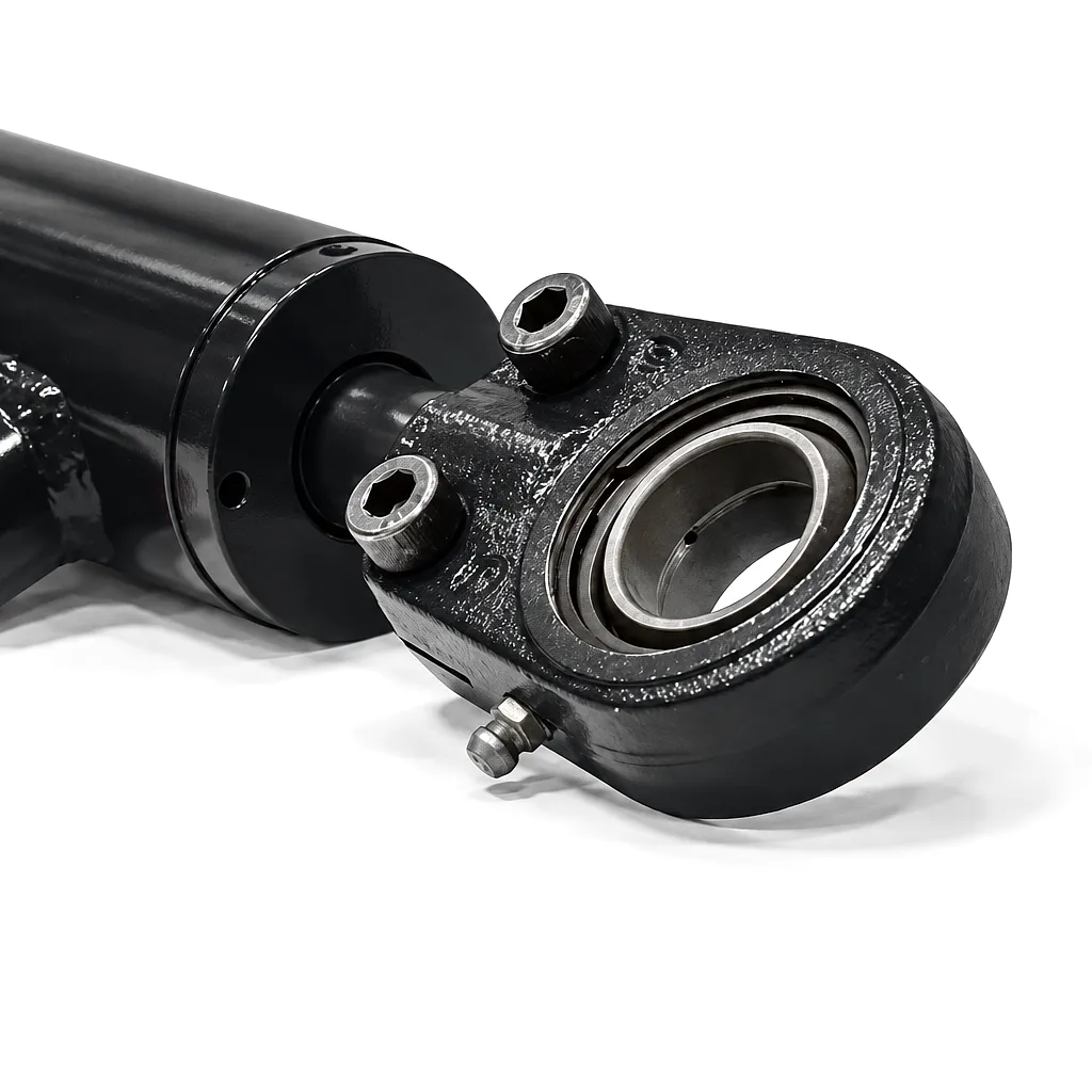
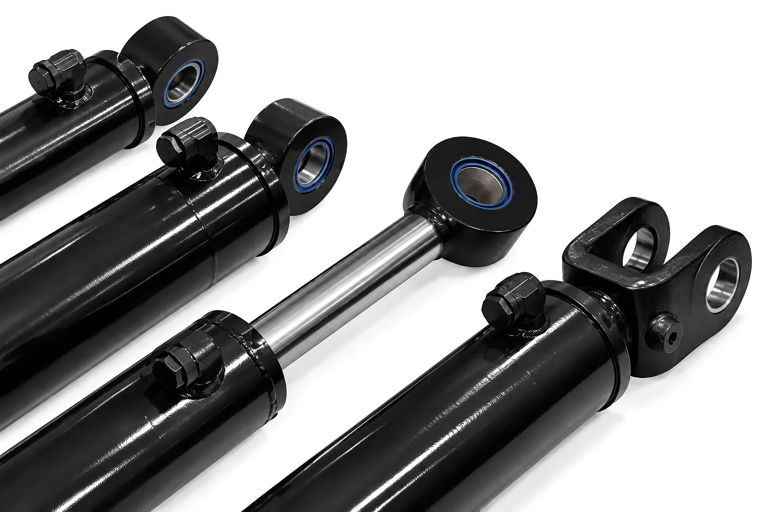
Crawler boom cylinders are commonly trunnion-mounted or pin-mounted at both ends, with dedicated lubrication points machined into the clevis ears and trunnion brackets. This rigidity is possible because the crawler superstructure provides a fixed, dimensionally stable mounting frame. Mobile crane cylinders must accommodate boom section articulation and use spherical self-aligning rod-end bearings that tolerate angular misalignment of up to 5 degrees, preventing bending moments that would otherwise propagate into the rod seal.
UK coastal and industrial environments demand more than standard chrome plating. Crawler crane cylinders deployed at port infrastructure projects — such as those along the Thames Estuary or at the Port of Grimsby — receive electroless nickel undercoat beneath hard chrome, boosting salt-spray resistance to exceed 500 hours by ISO 9227. Mobile crane rods destined for frequent road exposure in the Scottish Highlands or Welsh quarrying regions are increasingly specified with trivalent chrome or physical vapour deposition (PVD) ceramic coatings that outperform hexavalent chrome under REACH regulations.
Crawler crane boom cylinders are generally rated to a maximum working pressure of 350–450 bar, with hydraulic system relief valves set 10–15% below the cylinder’s proof-test pressure. The proof test itself — typically 1.5 times rated working pressure held for 5 minutes with zero drop — is performed on every unit before shipment and documented for CE marking under the Machinery Directive. Mobile crane cylinders must additionally pass dynamic fatigue testing, as their sequential extension and retraction cycles introduce far more pressure cycling than the relatively static operation of a crawler cylinder.
A crawler crane’s boom cylinder is accessible via the crane’s maintenance platform and is typically serviced in situ with a cylinder-specific seal kit and portable grinding equipment for minor rod scoring. Mobile crane telescopic cylinders, by contrast, must often be removed from the machine entirely and extended to full length — a procedure requiring a crane itself and a clean workshop floor of at least 30 metres — before the inter-stage seals can be replaced. This reality drives fleet managers at UK plant hire companies to maintain dedicated cylinder workshop bays.
Comparative Technical Performance Parameters
| Παράμετρος | Crawler Crane Boom Cylinder | Mobile Crane Boom Cylinder |
|---|---|---|
| Cylinder Type | Double-acting, single-stage | Single/double-acting, multi-stage telescopic |
| Bore Diameter Range | 160 mm – 360 mm | 80 mm – 280 mm (per stage) |
| Stroke / Extension | 2,500 mm – 6,000 mm | Up to 22,000 mm (multi-stage combined) |
| Πίεση εργασίας | 280 – 450 bar | 200 – 380 bar |
| Proof Test Pressure | 1.5× rated working pressure | 1.5× rated working pressure (per stage) |
| Rod Material | EN 10277 chrome steel, hard-chrome plated | ST 52-3 / EN 10210 alloy, chrome or PVD coated |
| Rod Surface Hardness | 850 – 1,000 HV | 750 – 900 HV |
| Seal Type | Quad-ring + PTFE composite piston seal | PU U-cup, inter-stage wiper + bearing rings |
| Θερμοκρασία λειτουργίας | -20°C to +80°C | -15°C to +70°C |
| Bore Surface Finish (Ra) | 0.4 µm or better | 0.4 µm or better (H8 tolerance) |
| Salt-Spray Resistance | ≥ 500 hours (ISO 9227) | ≥ 480 hours (ISO 9227) |
| Mounting Type | Trunnion / clevis pin, lubricated | Spherical rod-end bearing, swivel flange |
| Typical Service Interval | 4,000 – 8,000 operating hours | 2,500 – 5,000 operating hours |
| Compliance Standards | CE, PSSR 2000, ISO 6020/6022 | CE, PSSR 2000, ISO 6020/6022, dynamic fatigue |
Σενάρια Βιομηχανικών Εφαρμογών σε όλο το Ηνωμένο Βασίλειο
Crawler cranes with large-bore boom cylinders are the backbone of steel ladle handling and structural steel erection at Sheffield’s surviving heavy steel facilities and the large fabrication yards around Rotherham. These crawler boom cylinders must hold extreme static loads — steel ladles weigh in excess of 300 tonnes when full — for extended periods at consistent boom angles. The cylinder design must prevent any hydraulic drift that would allow a loaded ladle to descend uncontrolled, and the load-holding valves integrated into the cylinder circuit are rated for zero leakage under sustained load.
The offshore wind assembly hubs along the East Anglian coast and around Humberside represent one of the most demanding applications for crawler crane boom cylinders in the UK. Monopile sections and nacelle assemblies for offshore wind turbines can exceed 500 tonnes, and they must be lifted with precision within sea-swell movement windows. Boom cylinders in these applications are designed with additional internal cushioning at both ends of stroke to prevent mechanical shock when the crane operator reverses the boom movement during sea-state responsive rigging operations. Corrosion protection specifications are enhanced beyond standard to address the constantly salt-laden marine atmosphere.
Mobile cranes dominate urban construction across the UK’s major cities because they can self-deploy, travel between sites on public roads, and set up within the constrained footprint of an inner-city site. In London, Birmingham, and Manchester, mobile crane boom cylinders endure one of the most punishing duty cycles in the industry — multiple site moves per week, rapid boom deployment and retraction between lifts, and frequent partial-extension operation as the crane works at varying radii throughout each day. The telescopic boom cylinder seals in this application may complete tens of thousands of extension-retraction cycles annually, demanding seal compounds with excellent dynamic fatigue resistance and hydraulic fluid compatibility.
The UK’s major cargo ports rely on specialised crawler cranes for container handling, heavy project cargo placement, and ship-to-shore transfer of abnormal loads. Southampton’s port infrastructure handles roll-on/roll-off cargo that regularly requires precision crawler crane placement from a static position on the quayside. At Grimsby — a key hub for offshore energy sector equipment logistics — the boom cylinders on quayside crawler cranes are serviced to an enhanced schedule driven by the corrosive marine environment, with rod inspection and coating assessment performed every 1,000 operating hours regardless of visual condition.
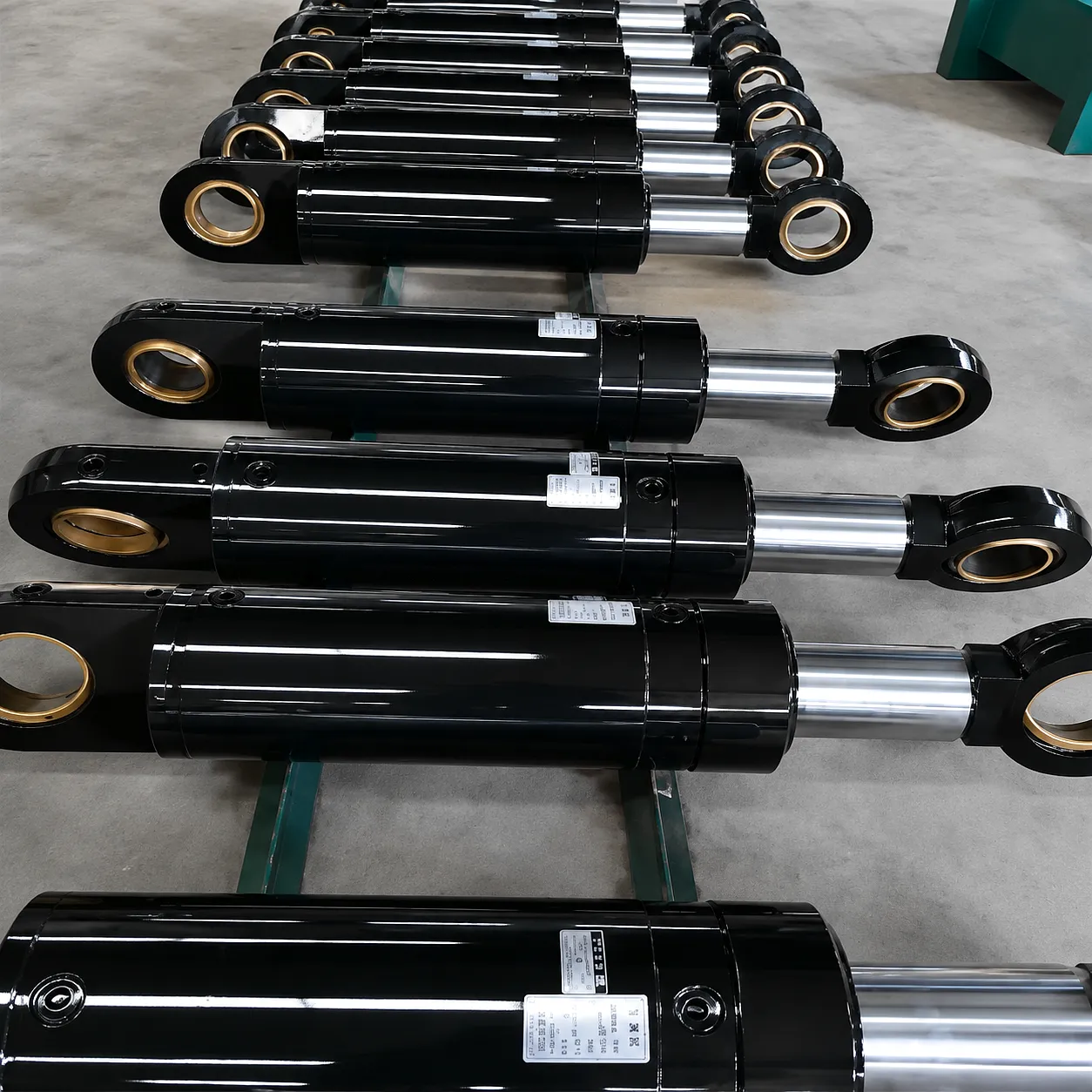 Ever Power has been engineering precision hydraulic boom cylinders for the international crane and lifting industry for over two decades, with a dedicated product engineering team that works directly with fleet operators, OEM crane manufacturers, and specialist lifting contractors to develop cylinders that meet exact specifications — not catalogue approximations. For UK customers, this means cylinders designed and tested to comply with PSSR 2000 (Pressure Systems Safety Regulations), CE-marked under the Machinery Directive, and shipped with full material certification traceable to the heat number of the steel bar stock from which the rod was machined.
Offshore Wind Assembly, Grimsby — Replacing a Worn Crawler Crane Boom Cylinder Under Time Pressure
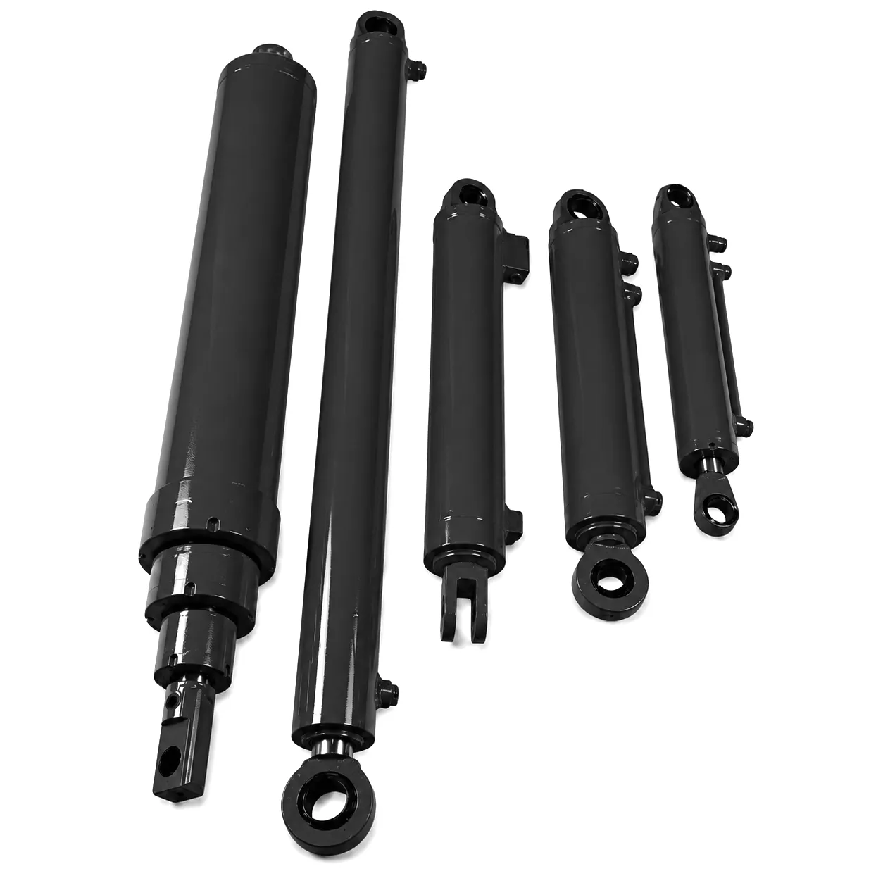 A specialist heavy lift contractor based in Grimsby, engaged in the assembly logistics for a major North Sea wind farm installation project, encountered a critical problem at the most commercially exposed moment of their annual contract cycle. One of their primary crawler cranes — a 600-tonne capacity machine positioned at the quayside — developed a visible rod seal failure on its boom cylinder during a scheduled maintenance inspection. The cylinder in question was a single-stage double-acting unit with a 280 mm bore and a 4,200 mm stroke, manufactured by the crane’s original European OEM. Sourcing a direct OEM replacement was quoted at a 14-week lead time, which would have resulted in breach of the project’s contractual lift window and substantial liquidated damages.
The contractor’s engineering manager contacted Ever Power after a recommendation from another UK plant hire operator. Within 48 hours, Ever Power’s technical team had reviewed the dimensional data, confirmed material and sealing compatibility with the crane’s existing hydraulic circuit, and proposed an exact-equivalent replacement cylinder manufactured from EN 10277 chrome steel with an upgraded PTFE-composite seal package rated to 420 bar. Production was expedited to 5 weeks, with the finished cylinder air-freighted to East Midlands Airport and delivered to the Grimsby site under an arranged logistics arrangement. The cylinder was installed, proof-tested, and cleared for operational use with 11 days remaining before the scheduled lift window — avoiding the liquidated damages entirely and preserving the contractor’s relationship with the project principal.
The replacement cylinder completed the remainder of the wind farm installation season — approximately 1,800 operating hours over six months — without any hydraulic leakage, rod surface degradation, or maintenance intervention beyond the scheduled lubrication of the trunnion pins. The Grimsby-based contractor subsequently placed a standing order with Ever Power for two spare cylinders to be held in their depot as insurance against future unplanned downtime on the same machine.
What UK Crane Operators Say About Ever Power
“The replacement boom cylinder arrived exactly within the quoted lead time and the dimensional match was perfect — no modifications needed to the existing trunnion brackets. After 2,000 hours of service, not a drop of hydraulic fluid on the rod. For a component that’s sitting under several hundred tonnes of steel, that kind of reliability is what we need.”
“We operate a mixed fleet of crawler and mobile cranes across sites from Aberdeen to the Midlands. Ever Power’s engineering team took the time to understand why our mobile crane telescopic cylinders were failing their inter-stage seals prematurely — it was a fluid contamination issue — and they redesigned the seal stack to accommodate our actual operating conditions. No other supplier offered that level of technical engagement.”
“Getting a custom cylinder with integrated position sensing built to our exact bore and stroke in under eight weeks was something we hadn’t seen from any European supplier. The material certs, pressure test records, and compliance documentation arrived with the cylinder, which meant our client’s site engineers accepted the component without question. That kind of paperwork discipline matters enormously on regulated construction sites.”
Product Advantages of Correctly Specified Boom Cylinders
Pilot-operated check valves and counterbalance valve integration prevent boom drift under sustained load, meeting LOLER 1998 requirements for safe rated capacity management.
CNC-honed bore surfaces at Ra 0.4 µm or better extend seal life dramatically by eliminating abrasive surface irregularities that are the primary cause of early seal failure.
Electroless nickel undercoat combined with hard chrome provides the salt-spray performance required by UK coastal and marine site operators without relying on environmentally restricted hexavalent chrome processes.
Every cylinder ships with CE Declaration of Conformity, proof test certificate, material traceability records, and dimensional inspection report — the complete document package required by UK principal contractors and PSSR 2000 Competent Person inspections.
Συχνές ερωτήσεις
Talk to Ever Power’s engineering team about your exact crane model, bore diameter, stroke requirement, and operating environment. We deliver CE-certified, fully documented boom cylinders to UK sites with competitive lead times.
 Greek
Greek  English
  Italian
  Portuguese
  Dutch
Dutch  Swedish
  Danish
  Finnish
  Polish
  Hindi
Hindi  Kazakh
  Turkish
  Ukrainian
  Romanian
  Spanish
  German
  Russian
  Korean
  Japanese
  Vietnamese
  Thai
Thai  Indonesian
  Malay
Malay  French