
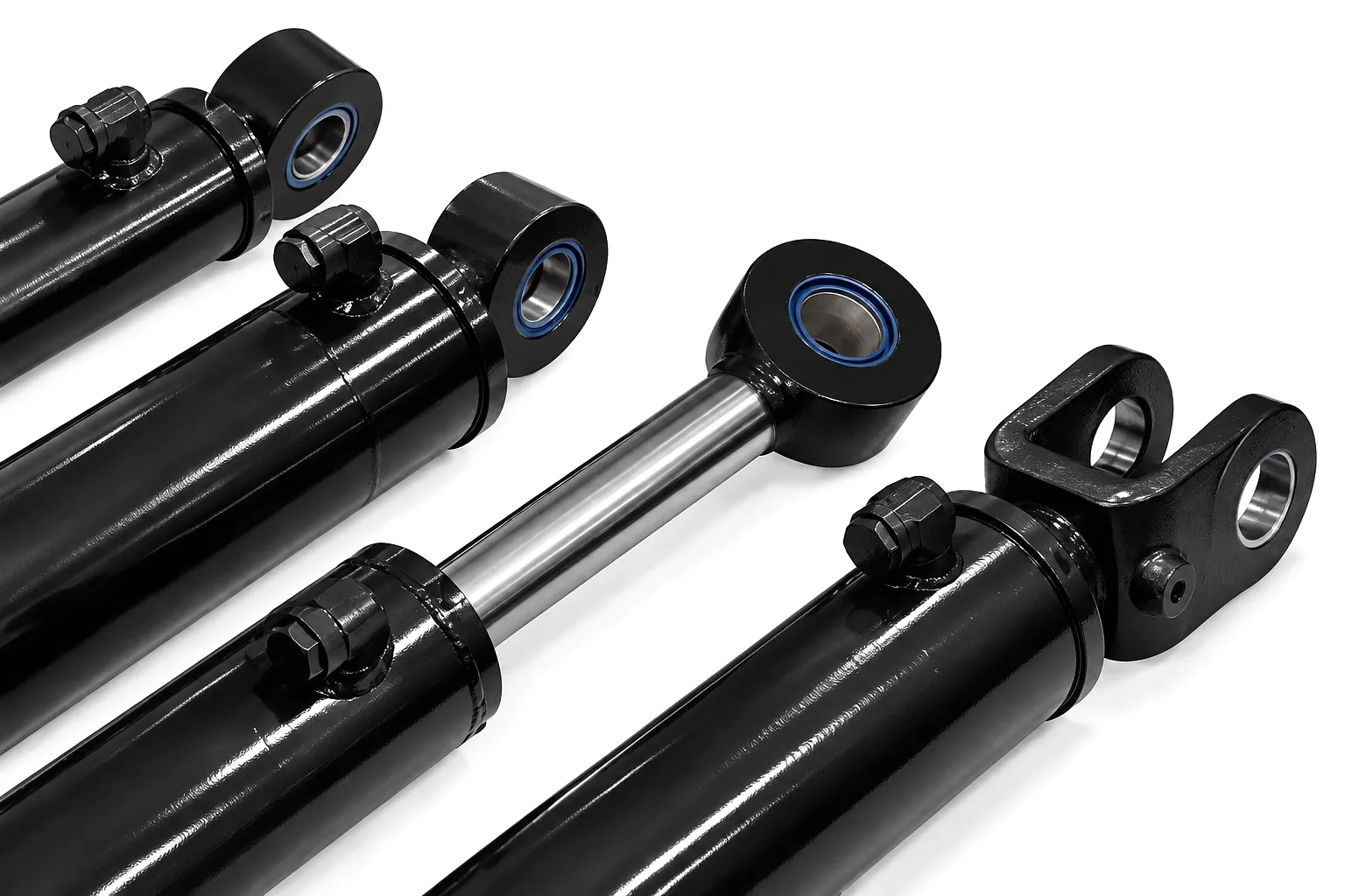
 Barrel swelling and distortion in hydraulic cylinders represent one of the most serious and often misdiagnosed failure modes in industrial fluid power systems. Across manufacturing plants in Birmingham, steel processing facilities in Sheffield, and offshore engineering operations throughout Aberdeen, maintenance teams frequently encounter cylinders that have exceeded their operational limits — either through a sudden overpressure event or through the slower, insidious progression of metal fatigue. What makes this failure mode particularly dangerous is that the external signs can be subtle right up until catastrophic rupture or seal failure occurs. A barrel that has begun to distort outward loses its dimensional accuracy, compromising the internal bore geometry that pistons and seals depend upon. Once that geometry is compromised, every subsequent pressurisation cycle accelerates the damage.
What Barrel Swelling Actually Means in a Hydraulic System
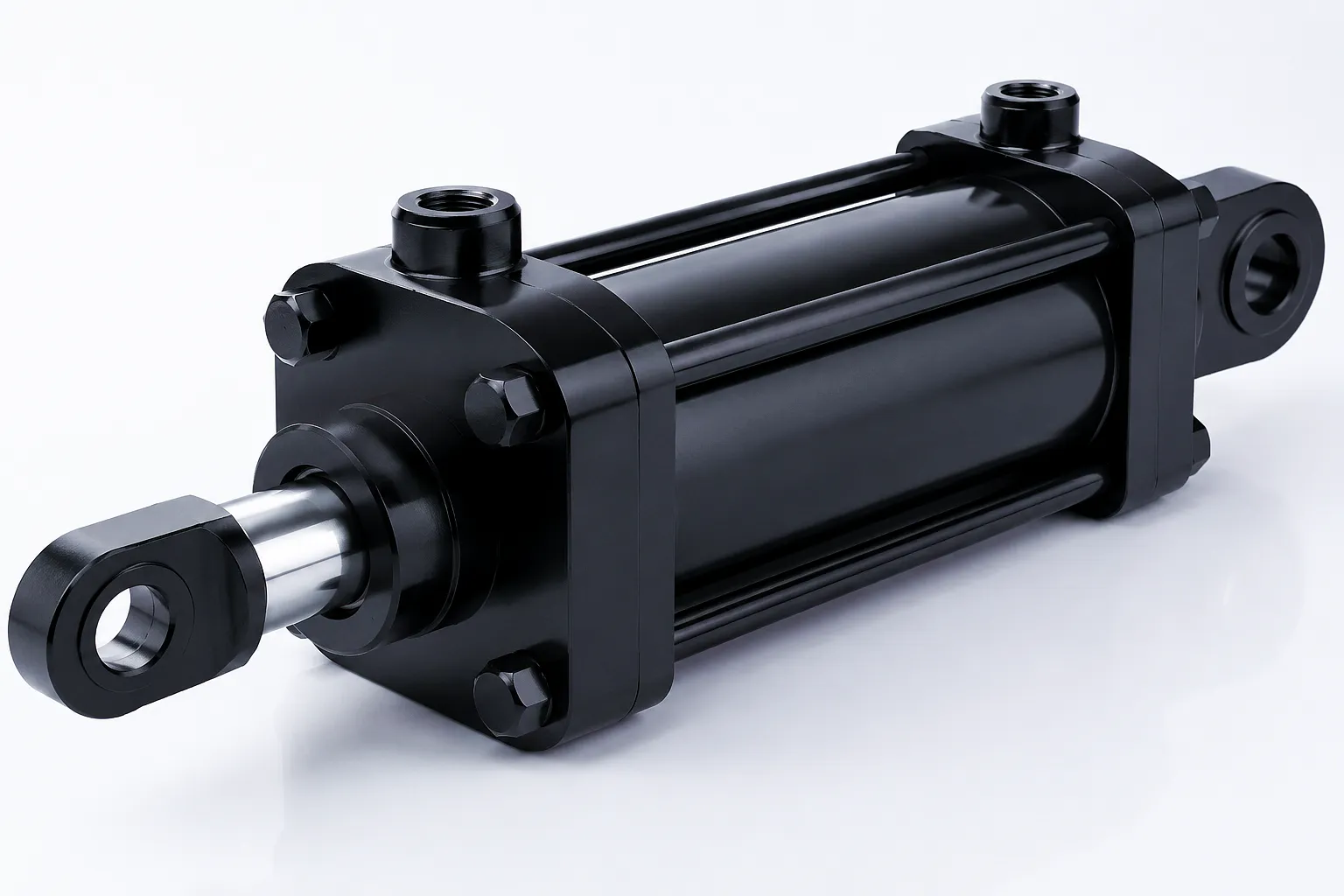 A hydraulic cylinder barrel is a precision-machined steel tube designed to contain pressurised fluid while guiding piston travel along a precisely defined bore diameter. When engineers refer to barrel swelling or distortion, they are describing a permanent plastic deformation of that tube wall — an outward bulging or an asymmetric change in bore geometry that was not present when the cylinder left the factory. The distinction between elastic deformation (which every pressurised cylinder experiences temporarily during each stroke) and plastic deformation (which is irreversible and structural) is critical. Elastic expansion under rated working pressure is designed into the cylinder’s safety factor. Plastic deformation is not — it signals that the stress applied to the barrel wall has exceeded the yield strength of the steel at that location, permanently rearranging the crystalline grain structure of the material.
In practice, UK maintenance engineers most commonly detect barrel swelling through dimensional inspection using bore gauges or through the premature failure of piston seals. A swollen barrel presents a bore that is slightly wider than the specified tolerance at the distorted section, often with a slight taper or ovality rather than a perfectly round expanded bore. Seals riding through that zone experience inconsistent contact pressure, generating heat, accelerating wear, and ultimately failing to maintain the pressure boundary. The fluid leakage that results is not just an efficiency loss — in hydraulic systems operating at 250 to 350 bar, as is common in UK press tooling and injection moulding applications, an uncontrolled leak path represents a serious safety and fire hazard.
Overpressure: How a Single Pressure Spike Damages the Barrel Wall
Overpressure events are the most immediate and dramatic cause of barrel swelling, and they occur more frequently in UK industrial environments than most maintenance schedules account for. Hydraulic systems are dynamic — when a piston reaches end of stroke and there is no compliant cushioning, the kinetic energy of the moving load and oil column must be absorbed somewhere. In systems without adequate pressure relief or end-of-stroke cushioning, that energy manifests as a hydraulic shock wave — a pressure transient that can exceed the system’s rated working pressure by a factor of three to five times, lasting only milliseconds but carrying enormous destructive potential. At 250 bar working pressure, a transient spike to 750 or even 1,000 bar is physically possible in poorly designed or maintained systems.
The barrel wall responds according to the Lamé equations for thick-walled cylinders. At rated pressure, hoop stress (the circumferential tensile stress in the barrel wall) remains within the material’s elastic range. When the transient spike occurs, hoop stress jumps proportionally, and if it exceeds the yield strength of the steel — typically 700 to 900 MPa for the E355 seamless cold-drawn steel used in quality hydraulic cylinder manufacture — the wall begins to yield. The outermost fibres of the wall, which carry the highest stress in a cylinder under internal pressure, deform plastically first, followed by the inner bore surface if the spike is severe enough. The result is a permanently larger bore diameter at the affected section, often accompanied by a slight reduction in wall thickness due to material redistribution.
A single significant overpressure event can render a hydraulic cylinder dimensionally out of tolerance without producing any immediately visible external signs. The barrel may look intact from the outside, but bore gauging will reveal the truth. In Sheffield’s steel rolling mills, where hydraulic cylinders drive screwdown and roll balancing systems at operating pressures approaching 300 bar, a single catastrophic load reversal — perhaps caused by a cobble in the rolling line — can produce exactly this kind of hidden damage. The cylinder continues to operate, but seal life drops from thousands of hours to weeks, and the reduced wall section offers significantly lower burst safety margins for all subsequent pressure cycles.
Metal Fatigue: The Slow Accumulation of Cyclic Stress Damage
If overpressure represents a sudden assault on the barrel wall, metal fatigue is a siege — patient, invisible, and ultimately just as destructive. Every time a hydraulic cylinder pressurises and depressurises, the barrel wall cycles through a stress range: from a low stress state when the system is at rest or low load, up to the full hoop stress at working pressure, and back down again. Each cycle does not cause immediate visible damage, but it initiates and propagates microscopic cracks within the steel’s grain boundaries. This is classical fatigue failure mechanics, described by the Wöhler (S-N) curve, which defines the relationship between stress amplitude and the number of cycles a material can withstand before failure.
For hydraulic cylinders operating in high-cycle applications — injection moulding presses in the West Midlands, automated transfer presses in Coventry’s automotive supply chain, or packaging machinery lines in Leicester — cycle counts of five million or more per year are not unusual. At these cycle rates, even stress amplitudes well below the material’s static yield strength can initiate fatigue cracking. The fatigue crack typically nucleates at a stress concentration — a surface defect on the bore, a machining mark, a corrosion pit, or a weld heat-affected zone in welded barrel constructions. The crack then propagates radially through the barrel wall with each successive pressure cycle. In the early stages, it may be visible only with dye penetrant or magnetic particle inspection. As it progresses, the remaining wall cross-section shrinks, local stress concentrations around the crack tip increase, and the crack accelerates. The end stage is either a through-wall crack with visible external leakage, or a sudden burst if the remaining ligament reaches critical fracture toughness.
Barrel distortion from fatigue often presents differently from overpressure distortion. Fatigue-damaged barrels may show a localised bulge near a specific feature — end cap threads, port bosses, or weld zones — rather than the more diffuse swelling associated with gross overpressure. The location of the distortion is itself a diagnostic indicator: swelling near the mid-stroke position often suggests sustained overpressure, while distortion concentrated at geometric discontinuities points towards fatigue initiation at stress concentration sites. For UK maintenance engineers developing predictive replacement schedules, understanding this distinction enables more targeted inspection protocols and smarter procurement timing.
⚛
Heavy Duty Single Acting Cylinders — Engineered for UK Industrial Demands
⚙
Custom Double Acting Telescopic Cylinders — Lifting Platform Solutions
Core Materials and Their Role in Barrel Integrity
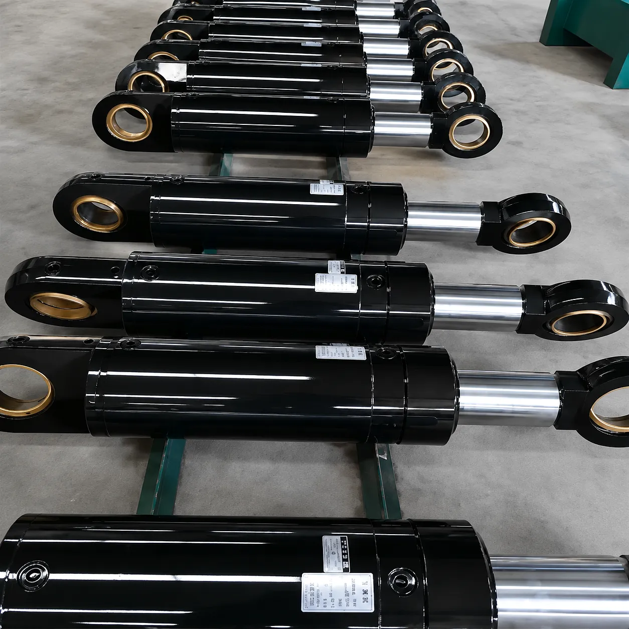
The resistance of a hydraulic cylinder barrel to both overpressure-induced swelling and fatigue-driven cracking is overwhelmingly determined by the quality and specification of the barrel tube material. The industry standard for high-pressure hydraulic cylinder barrels is EN 10305-1 cold-drawn seamless steel tubing, most commonly specified as grade E355 (formerly known as St52-3 under DIN standards). This designation indicates a minimum yield strength of 355 MPa, a tensile strength range of 490 to 630 MPa, and critically for fatigue performance, a fine-grained microstructure achieved through the cold-drawing process that closes any porosity in the original billet material. The cold-drawing operation also introduces beneficial residual compressive stresses at the bore surface, which act to slow fatigue crack initiation — a key reason why cold-drawn tube is specified over hot-rolled alternatives for demanding applications.
For applications requiring greater pressure capacity or higher fatigue life — such as the hydraulic actuators used in North Sea offshore equipment serviced through Aberdeen, or the heavy-duty compaction cylinders in UK waste processing facilities — the barrel material may be upgraded to alloy steel grades such as 42CrMo4 (chromium-molybdenum steel), which achieves yield strengths above 650 MPa in the quenched and tempered condition. This material offers significantly higher resistance to both static overpressure and cyclic fatigue, but requires more sophisticated machining and heat treatment controls. The internal bore surface treatment is equally critical: honing to a roughness of Ra 0.4 µm or better ensures optimal seal contact while minimising the surface defects that serve as fatigue crack nucleation sites. Some manufacturers apply hard chrome or electroless nickel plating to the bore for enhanced corrosion resistance in moisture-laden environments.
End caps, which are welded or threaded onto the barrel and represent geometric discontinuities that concentrate stress, are often manufactured from normalised or quenched-and-tempered carbon steel or alloy steel. The integrity of the barrel-to-end-cap joint — whether threaded, flanged, or welded — is a primary fatigue initiation site and demands rigorous quality control at the manufacturing stage. UK engineering procurement teams specifying replacement cylinders should request material certifications (EN 10204 3.1 or 3.2 certificates) as a baseline quality gate, confirming that the barrel tube meets the claimed material specification through independent mill testing rather than relying on manufacturer declarations alone.
Hydraulic Cylinder Technical & Performance Parameters
| Παράμετρος | Standard Range | Heavy-Duty / Custom Range | Notes |
|---|---|---|---|
| Bore Diameter | 25 – 250 mm | 250 – 800 mm | Custom bore honing to Ra 0.4 µm |
| Μήκος πινελιάς | 50 – 2,000 mm | 2,000 – 8,000 mm | Longer strokes require anti-rotation & guidance |
| Rated Working Pressure | 160 – 250 bar | 250 – 500 bar | Proof pressure = 1.5× working pressure |
| Burst Safety Factor | 4:1 minimum | 5:1 – 8:1 | Higher factor for offshore / safety-critical use |
| Υλικό βαρελιού | E355 cold-drawn seamless | 42CrMo4 Q+T, 27MnCrB5 | EN 10305-1 / EN 10083-3 certified |
| Yield Strength (barrel) | 355 MPa (min.) | 650 – 900 MPa | Q+T alloy steels for pressure ≥ 350 bar |
| Wall Thickness Ratio (D/t) | 6:1 – 10:1 | 4:1 – 6:1 (heavier wall) | Thicker wall reduces hoop stress for given pressure |
| Θερμοκρασία λειτουργίας | -20°C to +80°C | -40°C to +120°C | Seal compound selection drives thermal range |
| Surface Finish (bore) | Ra 0.4 – 0.8 µm | Ra 0.2 – 0.4 µm | Finer finish extends seal life; reduces fatigue sites |
| Rod Material | C45E hard chrome plated | 42CrMo4 / Induction hardened | Chrome thickness 20–25 µm standard |
| Seal Package | Polyurethane / NBR | PTFE, HNBR, FKM (Viton) | Matched to fluid type & temperature range |
| Fatigue Life (cyclic) | 1 × 10⁶ cycles | 5 × 10⁶ – 20 × 10⁶ cycles | Autofrettage treatment extends fatigue life significantly |
Working Principle: Stress Distribution Through the Barrel Wall
To understand why barrels swell or crack under specific conditions, it is necessary to examine how pressurised fluid stresses are distributed through the barrel wall cross-section. When hydraulic pressure acts on the internal bore surface, it generates three principal stresses: hoop stress (circumferential, acting to expand the bore diameter), axial stress (longitudinal, acting along the cylinder axis), and radial stress (acting through the wall thickness). Of these three, hoop stress is by far the largest and is the primary driver of both overpressure yield and fatigue damage. For a thick-walled cylinder — defined as one where the ratio of inner radius to wall thickness is less than ten — the classical Lamé equations predict that hoop stress is highest at the inner bore surface and decreases through the wall thickness towards the outer surface. This means that fatigue cracks typically initiate at or near the bore surface, where stress amplitudes are greatest, and propagate radially outward through the wall.
This stress distribution has important practical implications. A bore surface scratch, corrosion pit, or honing mark that might seem cosmetically trivial is sitting at the highest stress point in the entire structure. Under cyclic loading, it becomes a stress concentration that can reduce fatigue life by 50% or more compared to a geometrically perfect bore. This is why bore surface finish specifications are not arbitrary — they are fatigue life management specifications in disguise. Advanced manufacturing techniques such as autofrettage (intentional overpressurisation of the barrel to induce plastic deformation at the bore surface, creating beneficial residual compressive stresses) can effectively relocate the peak cyclic stress away from the bore surface, substantially extending fatigue life without changing material grade or wall thickness.
Pressure relief valve (PRV) sizing and response time are the primary design safeguards against overpressure barrel damage. A PRV must be set to open at a pressure that provides adequate safety margin below the barrel’s yield pressure, and must have a flow capacity sufficient to prevent pressure rise from outrunning the valve’s opening speed. In UK hydraulic system designs, PRV settings are typically governed by the requirements of BS EN ISO 4413 (Hydraulic Fluid Power — General Rules and Safety Requirements), which mandates that systems be protected against overpressure at all times. Maintenance teams should verify PRV calibration annually as a minimum, recognising that a PRV that has drifted high in its set point — even by 10 to 15 bar — can significantly change the probability of reaching yield-inducing pressure levels during a transient event.
Core Technical Advantages of Correctly Specified Hydraulic Cylinders
Dimensional Stability Under Load
Correctly specified cylinder barrels maintain bore diameter within ISO tolerance class H8 or H7 throughout their rated service life. This ensures consistent seal contact geometry, predictable piston friction, and reliable positional accuracy in motion control applications — critical for CNC press tooling and robotic assembly systems operating across the UK’s advanced manufacturing sector.
High-Cycle Fatigue Resistance
Cold-drawn seamless tube construction with polished bore surfaces and optional autofrettage treatment delivers fatigue lives exceeding 5 million full-pressure cycles. This translates directly into longer replacement intervals, reduced unplanned downtime, and lower total cost of ownership — particularly valuable for three-shift operations in Birmingham’s automotive stamping and fabrication plants.
Proven Pressure Containment Integrity
Each cylinder undergoes hydrostatic proof testing at 1.5 times rated working pressure — a mandatory quality gate that validates barrel wall integrity, end cap joint strength, and seal performance before any unit leaves the factory. Documentation trails including material certificates, dimensional inspection records, and proof test reports are provided as standard for UK industrial and offshore applications requiring full compliance with BS EN ISO 10100.
Customisable End Configurations
Clevis, trunnion, flange, and foot mounting options, combined with a wide range of port sizes and positions, allow hydraulic cylinders to be configured precisely for retrofit or original equipment applications. Cushioning at both ends of stroke can be specified to reduce hydraulic shock and protect against the pressure transients that drive overpressure barrel damage — a critical consideration for high-speed or high-inertia applications.
Corrosion-Resistant Surface Engineering
Hard chrome rod plating, electroless nickel bore coating, and optional external paint or powder coat finishes protect against the humid, chemically aggressive environments found in UK food processing, water treatment, and coastal engineering applications. Corrosion pits on the bore surface are one of the most common fatigue initiation sites — surface protection is therefore directly linked to long-term barrel integrity and resistance to distortion under cyclic loading.
Full Traceable Compliance Documentation
Material certifications to EN 10204 3.1 or 3.2, dimensional inspection reports, weld procedure qualifications where applicable, and CE marking under the Pressure Equipment Directive (now retained in UK law as UKCA marking) ensure that hydraulic cylinders meet the legal and contractual requirements of UK industrial procurement, insurance underwriting, and HSE compliance audits.
Industrial Application Scenarios: Where Barrel Integrity Is Most Critical
Steel Rolling Mills — Sheffield & Scunthorpe
Screwdown actuators and roll balance cylinders in steel mills operate at up to 300 bar continuous, with frequent pressure reversals as the rolling load fluctuates across the width of each coil. These are arguably the most demanding fatigue environments for hydraulic cylinders anywhere in UK industry, and barrel distortion has historically been a root cause of costly unplanned mill stoppages. Alloy steel barrels with autofrettage treatment are the appropriate specification for this application, combined with active pressure transient suppression through accumulator circuits.
Automotive Press Tooling — Birmingham & Coventry
Transfer presses and stamping lines in the West Midlands automotive supply chain cycle their main hydraulic cylinders at rates of up to 20 strokes per minute across three shifts. At these duty cycles, fatigue life management becomes the primary design driver. Cylinders with bore diameters from 160 to 400 mm and working pressures of 200 to 280 bar are common in this sector, and barrel swelling — typically discovered during scheduled bore gauge inspection — is a leading indicator of approaching end-of-fatigue-life in these assets.
Offshore & Marine Applications — Aberdeen & Aberdeen Harbour
Hydraulic cylinders used in North Sea drilling equipment, subsea BOP (blowout preventer) actuators, and marine riser tensioner systems face the dual challenge of very high working pressures — up to 500 bar in some BOP applications — combined with saline corrosive environments that rapidly degrade bore surfaces and initiate fatigue cracking. The consequences of barrel failure in these applications extend far beyond equipment damage, making the specification of correct materials, coatings, and safety factors a matter of regulatory and operational necessity.
Agricultural Machinery — Lincolnshire & East Anglia
Combine harvesters, large round balers, and soil conditioning equipment across the UK’s arable heartlands operate their hydraulic cylinders in highly variable pressure environments. Sudden ground obstacles, jammed feed channels, or unexpected crop density changes generate pressure spikes that, if inadequately controlled by system relief valves, can initiate barrel yielding in cylinders not specified for shock loading. Reinforced cylinder designs with higher burst safety factors and improved cushioning are increasingly specified by UK agricultural equipment distributors to reduce costly in-field failures during the critical harvest window. See our Hydraulic Cylinders For Combine Harvester Machine for purpose-engineered solutions.
Lifting & Material Handling — Nationwide UK Logistics
Scissor lift platforms, dock levellers, and heavy-duty vehicle lifts across UK distribution and logistics facilities rely on hydraulic cylinders for safe load support. In these applications, the gradual creep of barrel distortion is particularly dangerous because the cylinder may appear functional until a sudden overload event coincides with a structurally compromised barrel wall, triggering catastrophic failure. Regular inspection cycles and replacement based on cyclic load history rather than calendar time are recommended. Our Custom Telescopic Hydraulic Cylinders For Lifting Platform are engineered specifically for these demanding applications.
Civil & Construction Plant — London, Manchester, Leeds
Hydraulic cylinders fitted to piling rigs, tunnel boring machines, and heavy construction cranes operating on major infrastructure projects across the UK encounter extremely varied load profiles, frequent rapid reversals, and exposure to contaminated environments. Barrel distortion in these machines typically manifests as accelerated seal consumption and position drift, often attributed to other causes before the barrel bore is actually measured. A structured condition-based maintenance approach that includes periodic bore inspection is the most effective strategy for managing this failure mode in mobile plant.
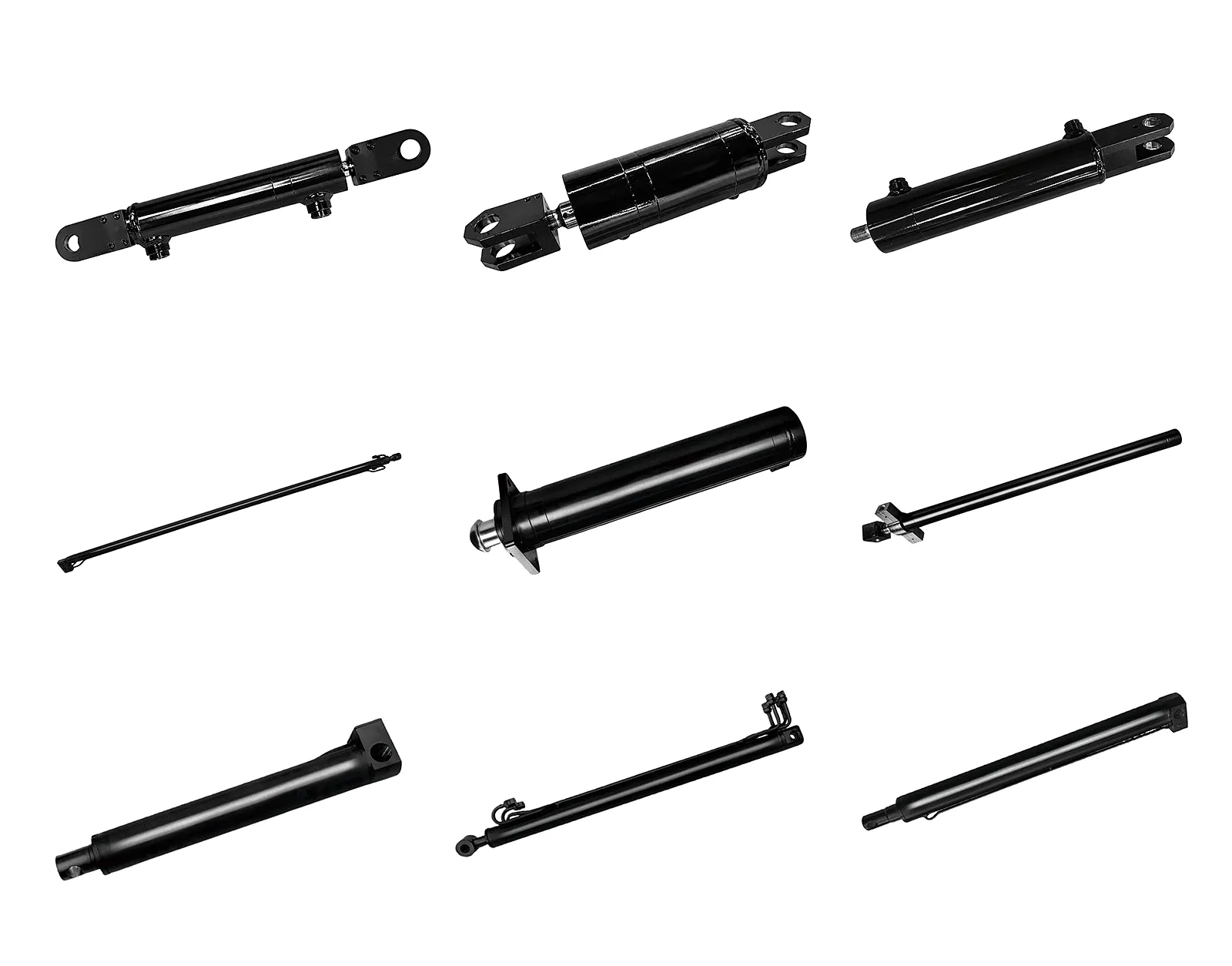
Ever Power Manufacturing: Precision, Customisation, and Supply Chain Assurance
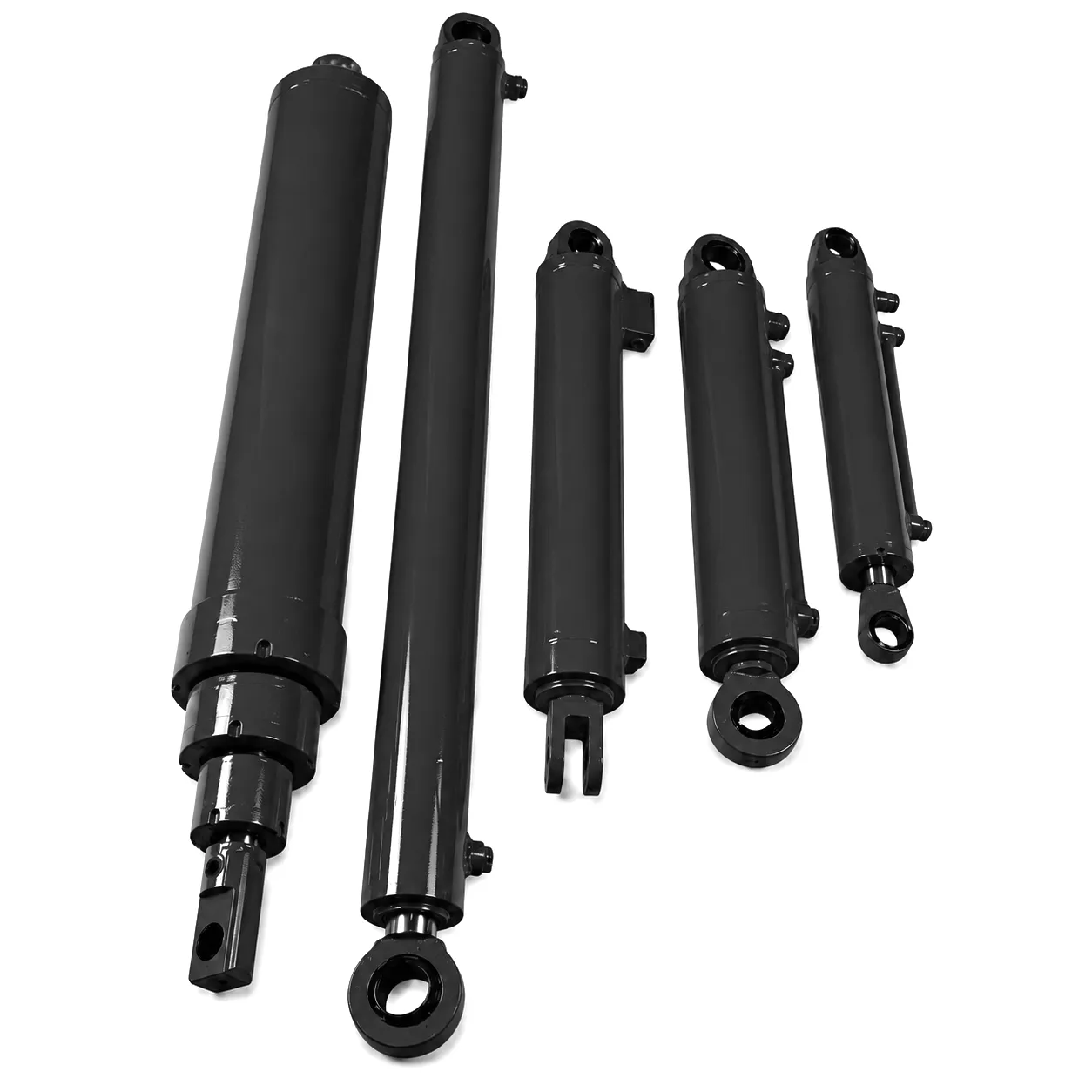 Ever Power has developed over two decades of precision manufacturing capability specifically focused on the demands of B2B hydraulic cylinder procurement for the UK, European, and global industrial market. The factory operates CNC deep-hole boring and honing lines that hold bore tolerances to within 0.01 mm across stroke lengths up to 8,000 mm, with bore surface finishes consistently achieving Ra 0.3 µm or better — a specification that directly translates into superior fatigue life and consistent seal performance over the full service life of each cylinder. Material traceability is maintained from bar stock selection through to finished product, with EN 10204 3.1 material certificates available as standard and 3.2 independent inspection certificates available on request for safety-critical or offshore applications.
Ever Power’s customisation capabilities extend across every dimension of hydraulic cylinder design. Bore diameters from 25 mm to 800 mm, stroke lengths from 50 mm to 8,000 mm, working pressures from 160 bar to 500 bar, and virtually any mounting configuration, port arrangement, or surface treatment can be engineered to customer specification. For UK maintenance engineers dealing with non-standard cylinder sizes resulting from original equipment that is no longer in production, this reverse-engineering capability — working from a damaged cylinder sample or from original engineering drawings — is a particularly valuable service. Ever Power’s engineering team can typically produce a dimensional specification for a custom replacement within 48 hours of receiving a dimensioned sketch or sample, with initial production units dispatched within three to six weeks depending on material and complexity.
The supply chain backing Ever Power’s customisation service includes partnerships with certified tube mills producing EN 10305-1 cold-drawn seamless tube in E355 and alloy steel grades, dedicated seal supply agreements with European seal manufacturers covering the full range of polyurethane, PTFE, HNBR, and FKM compounds, and a finishing and plating facility capable of hard chrome plating to 20 µm or greater thickness on rod diameters from 16 mm to 350 mm. For UK customers requiring rapid replacement of failed cylinders to minimise production downtime, Ever Power maintains a programme of semi-finished barrel tube blanks in the most common diameter and wall thickness combinations, enabling finished cylinder delivery timescales significantly shorter than standard lead times for custom work.
Customer Success Story: Resolving Recurrent Barrel Distortion in Sheffield Steel Processing
Sheffield, South Yorkshire — Heavy Metal Processing & Rolling
A major flat-rolled steel processing facility in Sheffield had been experiencing recurring hydraulic cylinder failures on their slitting line hydraulic clamp and tension bridle actuators. Over an 18-month period, the maintenance team had replaced four cylinder assemblies on a single press — a pattern that pointed clearly to a systemic problem rather than isolated component defects. Each failed cylinder showed the same failure signature: measurable bore swelling between 0.15 mm and 0.22 mm over a 200 mm section of the barrel mid-stroke, accompanied by catastrophic piston seal failure and hydraulic fluid contamination of the drive system. The operating pressure was 220 bar, within the cylinders’ rated working pressure of 250 bar, and the system had been signed off as compliant at installation. There was no obvious explanation for the recurrent failures — until the maintenance engineering team consulted Ever Power.
Ever Power’s technical team reviewed the application data, the failed cylinder dimensions, and the hydraulic circuit schematic. The root cause was identified within the circuit design: the pressure relief valve protecting the clamp circuit had a response time of 120 milliseconds — far too slow to limit the pressure transients generated when the slitting blades occasionally seized on harder-than-expected coil material. Pressure spike analysis using a data logger connected to a port tee showed transient pressures reaching 480 bar during blade seizure events — more than twice the rated working pressure and well into the plastic deformation range for the E355 barrel material originally specified. The solution involved two elements: replacement of the existing PRV with a faster-acting poppet-type valve with a response time under 15 milliseconds, and replacement of the barrels with Ever Power custom cylinders built from 42CrMo4 alloy steel in the quenched and tempered condition, providing a yield strength of 780 MPa and a fatigue life more than triple that of the original E355 specification at the observed transient pressure levels. Since installation, the Sheffield facility has operated for over 26 months without a single cylinder replacement — a performance record that has been incorporated into their planned maintenance scheduling as a benchmark.
“We specified Ever Power’s 42CrMo4 cylinder barrels for our bridle press actuators after the E355 units kept failing. The difference in bore dimensional stability is measurable — we’ve now run 26 months without a barrel replacement, compared to a previous average of less than five months between failures. The engineering support during specification was exceptional; they identified the PRV response time issue that our own team had missed.”
— Senior Maintenance Engineer, Flat Rolled Steel Processing, Sheffield
“The custom reverse-engineering service saved our production schedule. We had a non-standard cylinder on a 1990s transfer press with no drawings available — Ever Power reverse-engineered the bore, stroke, and mounting from the damaged unit and had replacement cylinders on-site within four weeks. Material certs to EN 10204 3.1 were provided without asking, and bore gauge inspection on arrival confirmed tolerances within 0.008 mm of nominal. Very impressive turnaround for a genuinely difficult job.”
— Plant Engineering Manager, Automotive Stamping Facility, Birmingham
“We procure hydraulic cylinders for offshore subsea equipment serviced out of Aberdeen, which means every cylinder needs full material traceability and proof test documentation. Ever Power provided EN 10204 3.2 certificates from an independent inspection body without any premium being charged over standard pricing. The cylinders themselves have performed flawlessly through 14 months of North Sea service — no measurable bore change, no seal degradation, no issues at all. We’ve now standardised on Ever Power for all our hydraulic actuator procurement.”
— Procurement Director, Subsea Equipment Services, Aberdeen
Inspection Protocols and Prevention Strategies for UK Maintenance Teams
Preventing barrel swelling and distortion requires a two-pronged approach: effective in-service inspection to detect early-stage damage before it progresses to functional failure, and system-level pressure management to eliminate or limit the overpressure events that initiate plastic deformation. The most direct inspection method for barrel swelling is internal bore gauging using a dial bore gauge or an air gauge calibrated to the cylinder’s specified bore diameter and tolerance class. A bore increase of 0.05 mm or more above the upper tolerance limit at any measured position is a reliable indicator of initial plastic deformation and should trigger a replacement decision, even if the cylinder is still sealing and functioning mechanically. UK industrial practice increasingly supplements bore gauging with ultrasonic wall thickness measurement, which can identify thinning associated with corrosion or external mechanical damage without requiring the cylinder to be disassembled.
For high-cycle applications, a cyclic maintenance approach using cycle counting rather than calendar-based replacement is more technically rigorous. Once the fatigue life of a cylinder design is known — either from manufacturer data, finite element analysis, or field experience — a replacement threshold can be set at 70 to 80% of the expected fatigue life, ensuring replacement before fatigue damage accumulates to a stage where distortion or cracking becomes likely. Data acquisition systems monitoring hydraulic pressure can simultaneously log cycle counts and flag high-amplitude pressure events, providing the empirical basis for both condition-based replacement scheduling and root cause analysis of premature fatigue failures.
Pressure transient management at the system design level is the most effective long-term prevention strategy. Specifying PRVs with appropriately fast response times and adequate flow capacity, installing hydraulic accumulators to absorb shock energy in high-inertia applications, and designing in adequate end-of-stroke cushioning are all measures that directly reduce the peak stress applied to barrel walls during operation. For UK plants reviewing existing hydraulic system designs, a hydraulic shock analysis — using either instrumented data logging or simulation software — is a worthwhile investment that often reveals surprisingly high transient pressures that maintenance teams have no awareness of, since the events are too brief and too fast to be noticed by human observation or standard pressure gauge monitoring.
Συχνές ερωτήσεις
Ever Power — Precision Hydraulic Cylinders for UK Industry
Ready to Solve Your Cylinder Barrel Challenges?
Our engineering team is ready to review your application, diagnose failure root causes, and specify the right cylinder solution — with material certificates, proof test documentation, and UK-ready lead times.
επεξεργασία από gzl
 Greek
Greek  English
  Italian
  Portuguese
  Dutch
Dutch  Swedish
  Danish
  Finnish
  Polish
  Hindi
Hindi  Kazakh
  Turkish
  Ukrainian
  Romanian
  Spanish
  German
  Russian
  Korean
  Japanese
  Vietnamese
  Thai
Thai  Indonesian
  Malay
Malay  French