
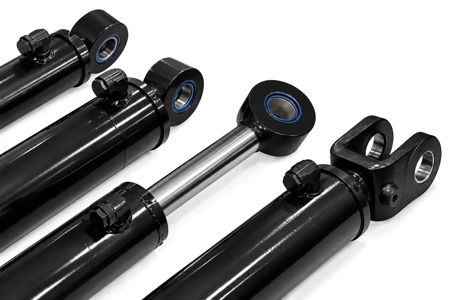
How Hydraulic Cylinder Seals Actually Work — and Why They Fail
A hydraulic cylinder converts pressurised fluid energy into linear mechanical force. The piston divides the cylinder barrel into two fluid chambers; controlled pressure differential across those chambers drives the piston rod in or out. The entire system depends on seals maintaining that pressure differential. Rod seals prevent fluid escaping along the piston rod as it traverses the gland; piston seals prevent bypass flow between the two chambers; wiper seals exclude contamination from entering as the rod retracts. Each seal type experiences different loading patterns, different chemical exposures, and different thermal cycles — which is why a single failure can rapidly cascade if not addressed at the source.
Seal degradation follows several distinct pathways. Thermal hardening and cracking is the most common in intermittent-duty plant equipment. Extrusion damage — where seal material is forced into the clearance gap between rod and gland — typically points to pressure spikes or incorrect seal groove dimensions. Abrasion on the rod or barrel bore surface indicates either contaminated fluid or the gradual breakdown of the wiper seal allowing ingress of mill scale, grit, or atmospheric particles. Chemical attack from incompatible hydraulic fluids is less common but devastating when it occurs, particularly in older plant that has been re-oiled without checking seal compound compatibility. Identifying the failure mode before replacing seals is essential — fitting new seals into an unchanged environment will reproduce the same failure within weeks.
Seal Materials: Choosing the Right Compound for Your Application
The seal compound is not a cosmetic detail — it determines whether a replacement seal survives six months or six years. Hydraulic cylinder seals are manufactured from a range of elastomeric and thermoplastic materials, each with defined performance envelopes that must be matched to the operating environment. Selecting the wrong compound is one of the most frequent errors made during in-field seal replacement, particularly when procurement teams order generic seal kits without reference to the original equipment specification.
The industry-standard choice for mineral oil and water-glycol systems. Operating range approximately -40°C to +120°C. Excellent resistance to petroleum-based fluids. Not compatible with phosphate ester fluids or fire-resistant synthetic oils.
Preferred for high-temperature and chemically aggressive environments. Operating range up to +200°C. Outstanding chemical resistance across a broad solvent spectrum. Preferred for steel manufacturing and foundry environments where ambient temperatures are consistently elevated.
Used primarily for guide rings and backup rings where dimensional stability and low friction are more critical than elasticity. PTFE blends reinforced with glass fibre, carbon, or bronze powder are common in precision cylinder applications and servo-controlled systems.
Exceptionally high wear resistance, making polyurethane the material of choice for mobile plant exposed to high side-loading and continuous duty cycles. Widely specified in construction equipment, agricultural machinery, and forestry plant operating throughout rural UK.
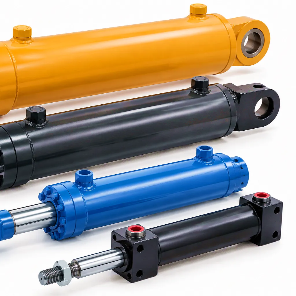
Tools Required for Hydraulic Cylinder Seal Replacement
Attempting seal replacement with improvised or inadequate tools is one of the fastest routes to damaging precision bores, scratching polished rod surfaces, or installing seals with twisted cross-sections that fail within hours of return to service. Before removing a single fastener, assemble the full tool set and verify that each item is serviceable. The list below represents the practical minimum for professional-grade work; workshop conditions will determine which additional items are needed for specific cylinder sizes or configurations.
Spanner wrenches (C-spanner or face spanner) matched to gland thread diameter; adjustable jaw type for field use. Bench vice with copper or aluminium jaw protectors rated for cylinder barrel diameter. Chain vice or V-block for large bore cylinders exceeding 150 mm bore. Torque wrench with appropriate range for retaining nut or gland torque specification (typically 80–800 Nm depending on cylinder size). Strap wrench for chrome-plated rod surfaces where jaw contact must be avoided.
Plastic seal pick set (90° and 45° angled picks) for removing old seals from grooves without scratching the land. Never use steel picks on precision surfaces. Seal installation cones machined or printed to match rod diameter — these protect lips during installation. Seal driver set for pressing O-rings and lip seals squarely into grooves. Calibrated digital vernier callipers for measuring groove depth and width prior to ordering replacement seals. Surface profilometer or Talysurf gauge if rod surface condition is in question.
Lint-free cleaning cloths and an approved hydraulic fluid flushing solvent compatible with the system’s operating fluid. Bright LED inspection light (ideally bore inspection scope for large cylinders). Magnifying glass or loupe for close inspection of seal grooves and contact surfaces. Fluid sampling kit if contamination is suspected as the root cause of seal failure — sending a fluid sample for laboratory analysis before refill can prevent repeat failures. Particle-free clean assembly bags for wrapping cleaned components during the seal replacement process.
Calibrated pressure gauge with 1.5x system working pressure range. Low-pressure hydraulic test rig or bench press for staged commissioning. Fitting caps and blanks appropriate to port thread standards (BSP is standard across most UK-sourced plant). Leak detection fluid or UV dye kit for confirming seal integrity at all port faces before full-load commissioning. Data logger or simple stopwatch for timing pressure hold tests against specification.
Hydraulic Cylinder Seal Performance Parameters — Reference Table
Step-by-Step Hydraulic Cylinder Seal Replacement Procedure
Depressurisation is not optional and must be verified, not assumed. Shut down the hydraulic power unit and engage any mechanical load locks or king pins that prevent cylinder drift. Open the circuit bleed points to release stored pressure, then operate the directional control valve manually in both directions to ensure the cylinder chambers are at zero gauge pressure. Measure with a calibrated gauge before proceeding. On accumulators or closed circuits, follow the specific OEM procedure — residual pressure in these systems can reach dangerous levels even with the pump stopped. Record the measured zero-pressure state in the maintenance log. UK workplace health and safety regulations (specifically the Provision and Use of Work Equipment Regulations) require this step to be documented for cylinders on public plant.
Cap all hydraulic port connections immediately after disconnecting fluid lines to prevent contamination ingress. Take photographs of the pin, clevis, bracket, and port orientations before removal — these reference images save significant time during reassembly, particularly on cylinders with angled port configurations. Clean the external surfaces of the cylinder thoroughly before bringing it to the work bench; mill scale, mud, and loose surface rust carried into the internal components during disassembly are a direct cause of premature seal failure on reassembly. The heavy-duty single-acting hydraulic cylinders manufactured by Ever Power incorporate chamfered port faces to facilitate cap fitting and reduce the risk of contamination during servicing operations.
Secure the cylinder barrel in the vice using jaw protectors. Apply penetrating fluid to gland threads if corrosion is suspected — leaving it to soak for 20 minutes rather than forcing the spanner is almost always faster in the long run. Unscrew the gland using the correct C-spanner or face spanner. As the gland clears the barrel threads, support the piston rod to prevent it dropping and contacting the bore wall. Withdraw the piston rod assembly smoothly and lay it on a clean, padded surface. Measure and record the rod diameter, surface finish condition, and any scoring before proceeding. On cylinders that have seen years of service, rod surface finish below Ra 0.4 micrometres in the seal contact zone means the rod requires re-chroming or replacement before new seals will achieve adequate service life.
Use plastic-tipped picks to lift and remove each seal from its groove. Lay the removed seals out in order on a clean white cloth — this preserves the exact installation sequence and orientation for reference during reassembly. Examine each seal systematically: look for extrusion damage at the high-pressure edge, heat crazing on the seal body, surface abrasion from rod scoring, and any signs of chemical swelling or shrinkage that indicate fluid incompatibility. Photograph notable failure modes for your maintenance records. With old seals removed, inspect every groove with a calibrated depth gauge and a loupe — groove dimensions must be within the manufacturer’s tolerance band before new seals are fitted. Oversized grooves from wear require cylinder rework, not a larger seal.
Warm lip seals gently in the system’s operating fluid (not hot water, which can distort seal geometry) to improve compliance during installation. Lubricate all seals and contact surfaces with clean system fluid immediately before fitting. Never use grease incompatible with the system fluid — grease contamination is a documented cause of hydraulic valve sticking in subsequent service. Feed each seal over the rod using the correct installation cone to protect the seal lip from the sharp thread chamfer at the rod end. Press seals into grooves using a seal driver or thumb pressure only — no sharp implements, no hammering. Verify that each seal is fully seated and correctly orientated before proceeding to the next. Buffer seals are directional; wiper seals must face the external environment. An incorrectly orientated piston seal will allow bypass immediately on pressurisation.
Reinsert the piston rod carefully, guiding it squarely into the bore without contact with the barrel wall. Thread the gland by hand first to verify clean thread engagement, then torque to the manufacturer’s specification in three equal stages. Reconnect fluid lines and bleed air from both cylinder chambers before applying working pressure. Commission in stages: bring the system to 25% of rated working pressure and hold for 5 minutes while checking all seals and port faces for weeping. Progress to 50%, then 75%, then rated working pressure, with a minimum 5-minute hold at each stage. Record gauge readings throughout. A pressure drop during a hold test that cannot be attributed to thermal effects indicates an incomplete seal — disassemble and investigate rather than accepting marginal results.
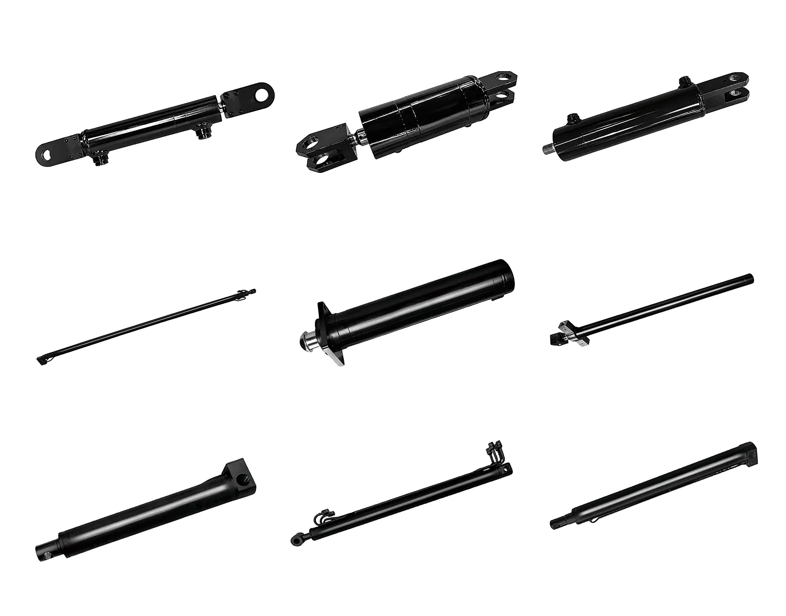
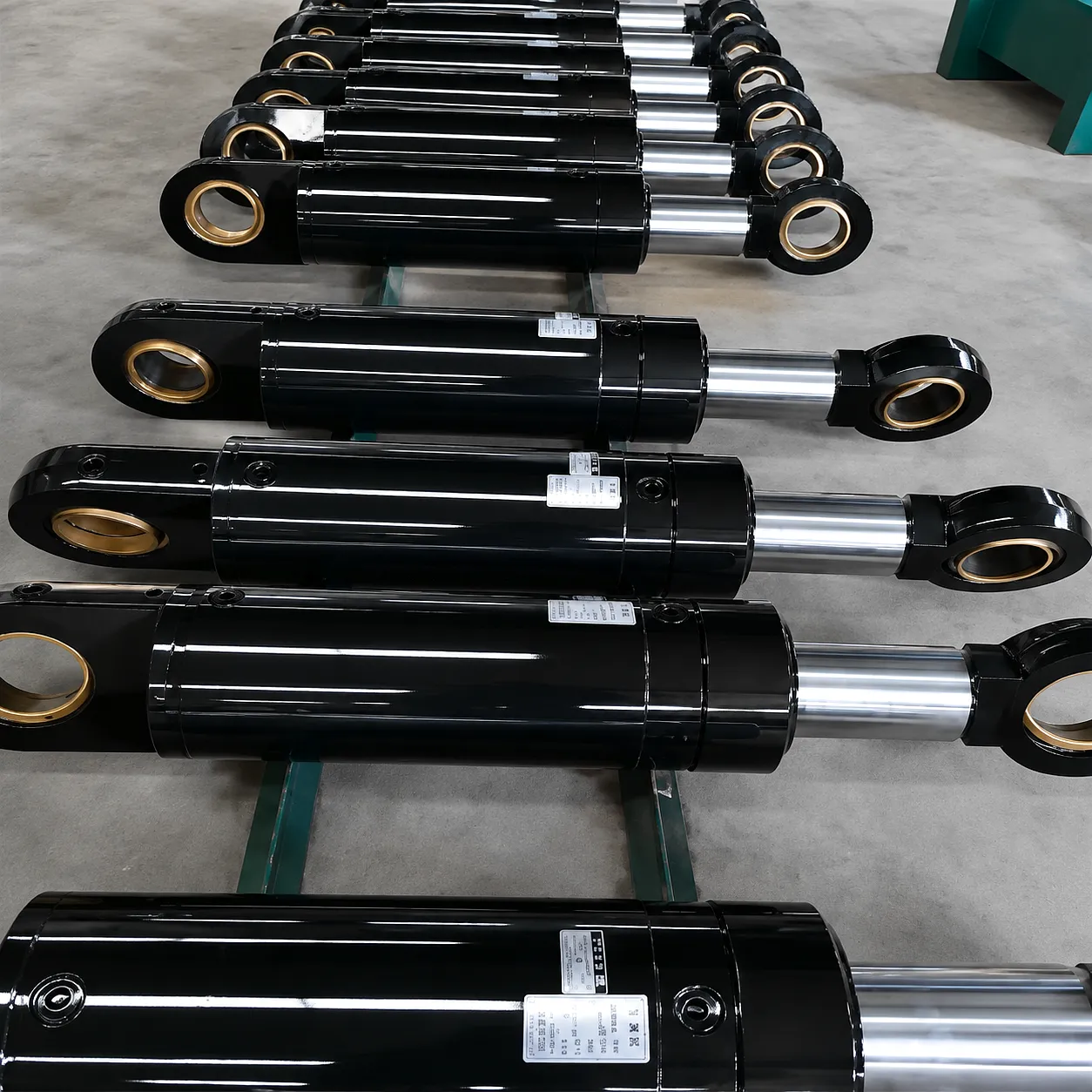
Common Seal Replacement Mistakes — and the Engineering Reasons to Avoid Them
Replacing seals without identifying why the original seals failed guarantees repeat failure. If pressure spikes caused extrusion damage, the relief valve setting needs checking. If fluid contamination caused abrasive seal wear, the filter specification and change interval need review. The seal replacement is a repair, not a solution, if the underlying condition remains unchanged. In demanding environments like the steel strip mills of South Yorkshire or the offshore support fabrication yards of Aberdeen, repeat seal failures are both expensive and a significant safety risk. Every seal replacement should begin with five minutes spent reading the failure evidence from the removed seals.
Dry installation creates microscopic cuts in the seal lip as it contacts thread edges and bore chamfers during assembly. These cuts become stress concentrations under pressure and cause early seal lip cracking. The rule is simple: every seal, every groove, and every contact surface should be thoroughly coated with clean system-compatible hydraulic fluid at the moment of installation. This applies regardless of the seal material or temperature conditions — dry assembly is never an acceptable shortcut, even when the maintenance window is tight and production pressure is high.
Ordering the cheapest available seal kit without verifying compound compatibility with the actual system fluid is a common procurement error with serious consequences. NBR seals fitted into a system running phosphate ester fire-resistant fluid will swell rapidly and disintegrate within days. FKM seals fitted where low-temperature flexibility is needed may crack on the first cold start in a UK winter when ambient temperatures drop below -15°C. Always cross-reference the seal compound against the fluid supplier’s compatibility data — most reputable UK fluid suppliers provide this data free of charge, and it takes under ten minutes to verify.
Gland overtorquing compresses the rod seal excessively, increases friction on the rod to levels that cause premature seal wear, and can plastically deform aluminium glands in lighter-duty cylinders. The feeling of a tightly torqued gland is not a guarantee of a leak-free joint — it is the seal geometry at the correct compression ratio that creates the seal, not brute force at the spanner. Always use a calibrated torque wrench and refer to the manufacturer’s figure. Where no manufacturer figure is available, Parker’s hydraulic cylinder service standards or Bosch Rexroth’s field service manuals provide appropriate default torque tables by gland thread size and material.
A scored or corroded rod surface is abrasive on every rod seal traversal. No seal compound is tolerant of sharp metal edges in the dynamic contact zone. Fitting new seals onto a damaged rod surface without attending to the rod condition is a confirmed path to seal failure within a small fraction of the expected service interval. Minor surface scoring in the sub-micron range can sometimes be addressed with a fine-grade honing cloth used in a circular motion; anything deeper requires a qualified rebuild including hard chrome stripping, re-grinding, and re-chroming to ISO 6945 surface finish standards.
The staged pressure hold test exists precisely to catch assembly errors before the cylinder returns to service where failure consequences are much more severe. Skipping the test to meet a production deadline is a risk management failure, not a time saving — a seal failure at working pressure during productive operation creates a much larger shutdown than a controlled bench test. The pressure hold test is also the right moment to check for port face weeping, check gland torque retention after the first thermal cycle, and verify that there is no abnormal friction in the rod movement that might indicate an overtorqued gland or a misaligned seal.
Industrial Application Scenarios — Where Hydraulic Cylinder Seal Replacement Expertise Matters Most
Combine harvesters, forage harvesters, and large-scale tillage equipment in the intensive arable farming regions of East Yorkshire and Lincolnshire operate under extreme seasonal loading. Seals on steering cylinders, header lift cylinders, and unloading auger actuators are exposed to field dust, straw particles, and wide ambient temperature swings from early spring to late harvest. The replacement protocol for these applications requires PU seals for abrasion resistance and reinforced wipers capable of handling particulate contamination. Maintenance windows are strictly constrained by the harvest calendar — having a certified replacement procedure and a pre-kitted seal inventory is essential. See also our hydraulic cylinders for combine harvester machines designed for exactly these operating conditions.
The remaining special steel and alloy steel producers of Sheffield, together with the pressing and stamping operations distributed across Birmingham and the wider West Midlands, operate hydraulic systems at sustained high pressures and elevated ambient temperatures. Cylinder seals in these environments are exposed to radiant heat from billet handling and induction furnaces, as well as mill-scale contamination from hot-rolling operations. FKM seals are the standard specification, and replacement intervals are typically shorter than in ambient-temperature environments. A structured preventive replacement programme — proactive seal kit replacement at defined intervals rather than reactive replacement after failure — consistently reduces total maintenance cost in these settings.
Excavators, telehandlers, concrete pump booms, and lifting platforms operating across the UK’s major infrastructure projects — from HS2 civil works to port expansion schemes — subject hydraulic cylinders to high-cycle duty with heavy contamination exposure. Custom telescopic hydraulic cylinders for lifting platforms on these sites typically use multi-stage seal replacement protocols due to the stacked seal groove arrangements in telescopic design. Plant managers on major sites increasingly contract out cylinder seal replacement to specialist service teams with mobile workshop capability — a trend driven by equipment warranty requirements and the cost of incorrect repair on high-value plant.
Hydraulic cylinders on vessels and offshore support structures along the North Sea coast and in the major river port systems of the Tyne, Clyde, and Thames face saltwater spray, UV exposure, and temperature cycling that is particularly demanding on rod seals and wiper seal compounds. Marine-specification seal kits use enhanced NBR or EPDM compounds with zinc-coated backup rings and stainless-steel gland hardware. Seal replacement in confined engine room or below-deck environments demands compact tool sets and strict fluid containment — hydraulic fluid contaminating bilge water is both a regulatory violation and an environmental liability under UK maritime law.
Ever Power — Precision Manufacturing and Hydraulic Cylinder Customisation
Ever Power operates advanced hydraulic cylinder manufacturing facilities with CNC deep-hole boring machines, precision honing lines, and fully equipped seal groove production cells capable of achieving groove tolerances to H8/f7 fits as standard. Our manufacturing process covers bore sizes from 25 mm through to 500 mm and stroke lengths up to 6,000 mm, with full traceability on all materials used across the cylinder assembly. Every cylinder that leaves our factory carries test certification for the specified working pressure range, including a pressure test at 1.5 times rated working pressure prior to dispatch.
Customisation is a core capability at Ever Power, not an afterthought. Our engineering team works directly with UK plant operators, OEMs, and procurement departments to design seal configurations, groove profiles, and material specifications around the actual operating environment. When a client in Birmingham comes to us with a failed cylinder from a high-temperature pressing application, our engineers review the failure, specify the appropriate FKM or PTFE-based seal stack, and design a gland configuration that provides the access needed for future in-field seal servicing. That attention to the lifecycle cost of maintaining a cylinder — not just its initial performance — is what distinguishes a thoughtfully engineered cylinder from a commodity component.
Our supply chain is structured to support urgent requirements from UK clients without the delays associated with standard ocean freight. Cylinders destined for UK agricultural customers are typically stocked in standard configurations with short lead times, while fully custom cylinders for heavy process industry and marine applications are manufactured to detailed technical drawings with delivery schedules agreed at order confirmation. Ever Power provides full documentation support — including material certificates, pressure test reports, and seal compound certification — as standard on all exported cylinders to meet UK import and quality assurance requirements.
Customer Success Story — Steel Tube Manufacturer, Sheffield, South Yorkshire
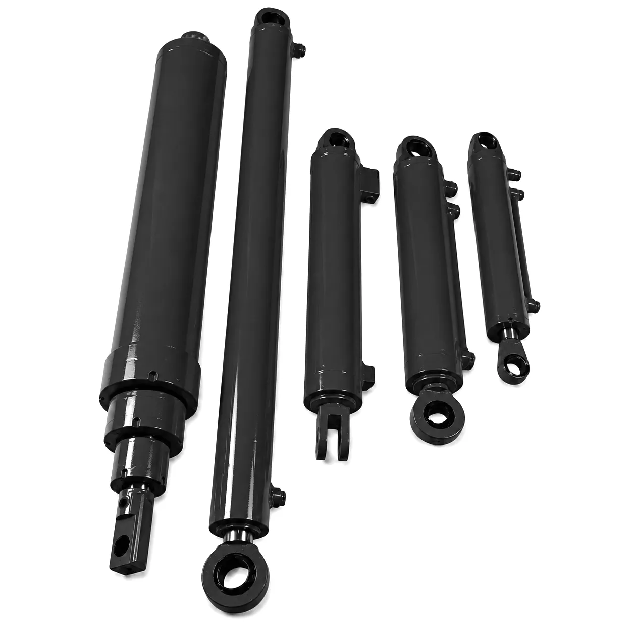
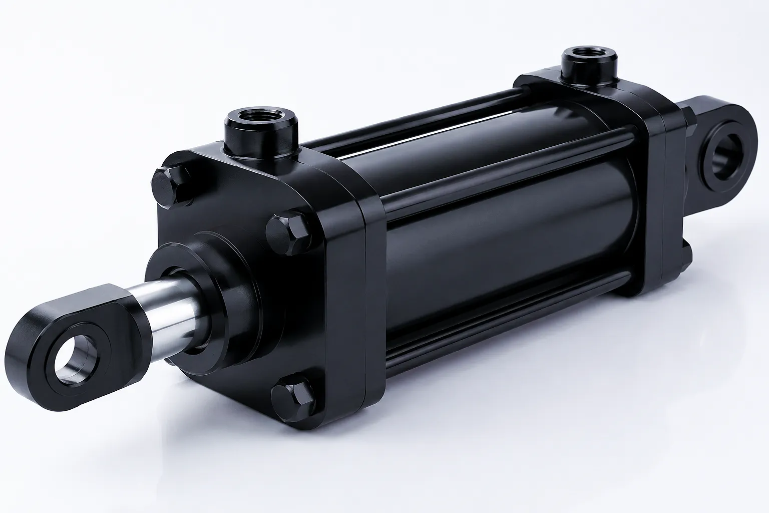 A mid-sized cold-drawn steel tube producer operating three draw benches in Sheffield had been experiencing repeated hydraulic cylinder seal failures on the drawbench clamping cylinders — typically six to eight weeks after each replacement. The cylinders operate at 280 bar working pressure with significant pressure cycling at every draw pass, and ambient temperatures in the draw bench area regularly exceed 60°C due to the proximity of the annealing furnaces.
The maintenance team had been using generic NBR seal kits purchased from a local hydraulic supplier. When they contacted Ever Power through the boom-cylinders.com platform, our applications engineer reviewed the cylinder specifications, the fluid analysis data the client had retained from the last two failure episodes, and the ambient temperature records from the drawbench area. The diagnosis was clear: NBR seals were reaching thermal hardening failure at the sustained 60–65°C operating temperature, compounded by pressure spikes that were causing extrusion damage at the high-pressure land of the piston seal grooves. The grooves themselves had also worn slightly beyond the H8 tolerance band over years of service.
Ever Power supplied replacement cylinders with FKM piston and rod seals, PTFE backup rings, and gland configurations machined to the correct groove tolerance from new bar stock. The cylinders were pressure-tested at 420 bar prior to despatch, and our technical team provided a revised maintenance procedure for the Sheffield maintenance team covering the correct torque settings, fluid compatibility verification steps, and a recommended staged pressure commissioning protocol. Twelve months after fitment, all three cylinders remain in service with no seal-related downtime.
Τι λένε οι πελάτες μας στο Ηνωμένο Βασίλειο
“Ever Power identified the root cause of our seal failures that three other suppliers had completely missed. The FKM upgrade they specified has transformed the reliability of our draw bench clamping system. Twelve months in, zero unplanned downtime related to cylinder seals. That is an extraordinary improvement for us.”
“The documentation package that came with our custom cylinders — pressure test certificates, material certs, groove dimension drawings — is exactly what our quality system requires. Procurement from Ever Power has been seamless, and the technical support via email has been genuinely impressive. These are people who actually understand hydraulics.”
“We needed a non-standard bore and stroke combination with a marine-grade seal spec for our shipyard lifting frame. Ever Power turned around a detailed engineering proposal within 48 hours of our enquiry and delivered cylinders to our specification within the agreed lead time. The pressure certification met Lloyd’s Register requirements without any additional paperwork. We will use them again.”
Συχνές ερωτήσεις
Talk to Ever Power’s engineering team about your specific application, cylinder dimensions, or replacement seal specification.
 Greek
Greek  English
  Italian
  Portuguese
  Dutch
Dutch  Swedish
  Danish
  Finnish
  Polish
  Hindi
Hindi  Kazakh
  Turkish
  Ukrainian
  Romanian
  Spanish
  German
  Russian
  Korean
  Japanese
  Vietnamese
  Thai
Thai  Indonesian
  Malay
Malay  French