
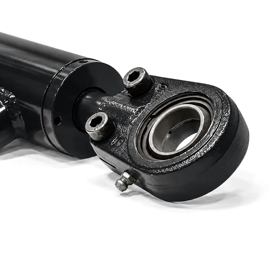
 Every hydraulic cylinder operating under load — whether it supports a platform fifty feet above a Birmingham construction site or holds a press in a Sheffield steel fabrication shop — carries an inherent risk: what happens when a hose bursts, a fitting fails, or a control valve malfunctions? The answer, in an unprotected system, is catastrophic and uncontrolled cylinder movement. It is precisely this failure mode that velocity fuses and load-holding valves were engineered to prevent. These two safety devices sit at the intersection of physics, precision manufacturing, and regulatory compliance, yet they are frequently misunderstood, misapplied, or selected on price alone — decisions that cost UK businesses far more than any quality component ever would.
Response within 24 hours · Custom specifications welcome · UK & international shipping
What Velocity Fuses Actually Do — and Why the Name Is Slightly Misleading
A velocity fuse — sometimes called a flow fuse or hydraulic fuse — is a passive, in-line safety device that automatically shuts off flow when the rate through it exceeds a pre-set threshold. The name “velocity fuse” is a useful shorthand, but what it actually senses is volumetric flow rate, not velocity in the strict fluid-dynamics sense. The internal mechanism is elegantly simple: a spring-loaded poppet or spool sits in a chamber matched to the cylinder’s normal operating flow. Under standard conditions the element holds open, flow passes freely, and the cylinder moves at design speed. When a downstream hose ruptures or a line fails, the cylinder — now under load with no back-pressure — begins to drop rapidly. Flow through the fuse spikes far above its set point, compresses the spring, seats the poppet, and flow stops. The cylinder stalls and holds position. No electrical signal, no solenoid, no software — just pressure differential and spring force doing physics.
The critical specification is the trip flow rate, and getting it right requires careful calculation. Set it too close to normal operating flow and the fuse trips during legitimate fast-extension cycles — a constant nuisance on high-cycle machinery. Set it too high and it fails to trip before dangerous cylinder movement occurs. The standard engineering practice is to set the trip point at 150–200% of the maximum normal operating flow, verified against the worst-case cylinder speed under full load with any control-valve metering removed. This range gives adequate safety margin against burst-hose scenarios while tolerating brief transient flow spikes that occur during normal direction changes. UK manufacturers supplying into CE-marked machine categories often need to document this calculation as part of their technical file under the UK Machinery Regulations 2008, particularly for working-at-height applications where a cylinder drop event would constitute a category-3 or higher risk.
Engineering Note: Velocity fuses mount directly at the cylinder port — not in a remote manifold — for maximum effectiveness. A fuse mounted anywhere other than at the cylinder port will not protect against hose failures between the fuse and the cylinder. This is one of the most common installation errors seen in the field, and it renders the device essentially non-functional for its primary safety purpose.
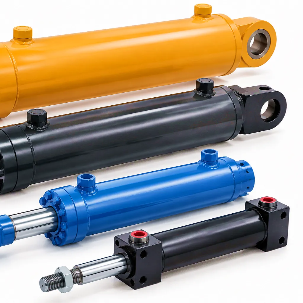
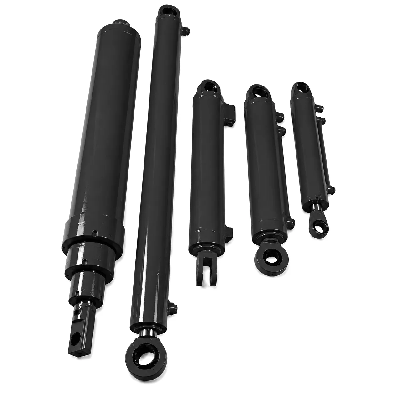
Engineered for aerial work platforms where velocity-fuse integration is a safety-critical requirement. 1458mm stroke, precision-honed bore, compatible with pilot-operated load-holding valve mounting at cylinder port.
Load-Holding Valves: Counterbalance, Pilot-Operated Check, and When Each Is the Right Choice
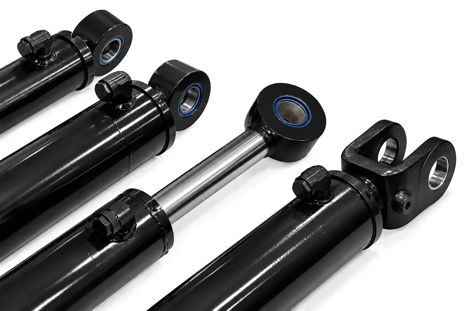
Load-holding valves address a different — but equally serious — failure mode. Where velocity fuses respond to catastrophic hose failure, load-holding valves manage controlled leakage under sustained static load. A cylinder holding a suspended load for hours or days will slowly drift if the control valve leaks internally, which virtually all directional control valves do to some degree. On a crane jib over a Manchester dockyard or a hydraulic press at a Midlands automotive stamping plant, that slow drift represents real danger and process interference. The two primary technologies are pilot-operated check valves and counterbalance valves, and while they are sometimes used interchangeably in conversation, they perform meaningfully differently in practice.
A POCV is essentially a standard check valve with a pilot port added. In its default state it blocks flow in the reverse direction (i.e., from the cylinder back to tank) with zero leakage — the poppet seats hard against its seat under load pressure. To allow the cylinder to retract or lower, a pilot signal from the opposite circuit line lifts the poppet and permits return flow. The result is a device that holds load with near-zero internal leakage indefinitely, releases cleanly on command, and is mechanically simple enough to have very long service life. POCVs are the preferred choice for static load-holding applications where load does not induce system instability — vertical cylinders holding fixed loads, jig clamps, horizontal slide locks, and fixed-position platform locks all suit this device well.
A counterbalance valve introduces a calibrated back-pressure on the load-bearing side of the cylinder. Unlike a POCV, which opens fully on pilot signal, a CBV modulates: it opens proportionally to the incoming pilot pressure, allowing smooth, metered descent even when a suspended load attempts to run away from the pump. This makes counterbalance valves the correct choice for dynamic load scenarios — mobile crane outriggers, aerial platform booms that must be lowered smoothly with a load on board, and any system where the load could drive the cylinder faster than the pump supplies flow to the other side. The trade-off is heat generation (the CBV continuously throttles flow under back-pressure) and the need for careful pilot-ratio and set-pressure specification to avoid instability. A poorly specified CBV will oscillate — a condition known as hunting — which is both damaging to the circuit and potentially hazardous.
Many modern hydraulic circuits deploy both device types simultaneously: a POCV for static load-holding integrity and a counterbalance valve downstream for dynamic descent control. Some manufacturers integrate velocity fuse functionality directly into the counterbalance valve body, producing a compact block that addresses hose-burst protection, thermal drift, and runaway load in a single port-mounted unit. Ever Power manufactures these combination valve blocks in SAE-O-ring and BSP configurations, with pilot ratios from 3:1 to 12:1 and set pressures adjustable at commissioning. For UK contractors working to Health and Safety Executive guidance on working-at-height equipment, this integrated approach significantly simplifies compliance documentation and reduces potential single-point failures in the hydraulic safety chain.
Working Principle: The Physics Behind Passive Hydraulic Safety
The operating principle of both velocity fuses and load-holding valves stems from the same foundational hydraulic relationship: pressure differential drives flow, and flow can be controlled by varying the restriction through which it passes. In a velocity fuse, the spring pre-load defines the pressure differential at which the poppet seats. As downstream resistance drops (due to a burst hose), inlet pressure rises relative to outlet, the pressure differential across the poppet increases, spring force is overcome, and the element closes. The process happens in milliseconds — fast enough to arrest cylinder movement before significant travel occurs.
In a pilot-operated check valve, the pilot pressure acts on a separate control piston that mechanically lifts the main poppet against load pressure. The pilot ratio — typically 3:1 to 4.5:1 for standard designs — means the pilot pressure required to open the valve is one-third to one-quarter of the load-induced pressure on the cylinder port. This ratio must be achievable by the system pump during a lowering operation; if the pump cannot generate sufficient pilot pressure (for instance, in a power-loss scenario), the POCV remains closed and the load stays supported. This behaviour is the functional basis of fail-safe operation in aerial work platforms, a requirement embedded in EN 280, the European standard adopted as UK standard BS EN 280, governing mobile elevating work platforms.
Q_trip = 1.5 × Q_max_normal
P_set = 1.3 × P_load_max
PR = P_load / P_pilot_required
HSE Note: UK Health and Safety Executive guidance (HSG245) recommends that any hydraulic system used for supporting persons must incorporate positive means of load retention that does not rely solely on a directional control valve’s internal spool sealing.
Core Materials: What Quality Velocity Fuses and Load-Holding Valves Are Made From
Ductile iron (EN-GJS-500-7) for medium-pressure applications up to 250 bar; forged carbon steel (SAE 1045 or equivalent) for high-pressure systems up to 400 bar. Marine and offshore-adjacent applications increasingly specify stainless steel 316L bodies to resist corrosion from salt-air environments along the UK’s coastal industrial zones.
Through-hardened alloy steel (Rockwell HRC 58–62 on seating faces), ground to Ra 0.4 µm or better. The poppet seat contact geometry — typically a 45° included angle — is lapped to ensure leak-tight closure within the first few operating cycles. Inferior poppets made from case-hardened mild steel wear rapidly under repeated high-pressure seating and are a common cause of load-holding valve failure in the field.
Chrome-silicon alloy spring wire (DIN 17223 / EN 10270-2), shot-peened and pre-set to eliminate early relaxation. Operating temperature range -30°C to +120°C, critical for outdoor UK applications where ambient temperatures vary significantly across seasons. Spring rate tolerance is held to ±3% in precision-grade velocity fuses to ensure consistent trip flow across production batches.
Nitrile (NBR) for standard mineral oil circuits operating below 80°C; FKM (Viton) for higher temperatures, biodegradable hydraulic fluids, or phosphate-ester fluids used in some UK aviation-adjacent and fire-resistant applications. PTFE back-up rings are standard on static seals in high-pressure assemblies to prevent extrusion under sustained load pressure.
Product Technical and Performance Specification Table
| Parameter | Velocity Fuse | Pilot-Operated Check Valve | Counterbalance Valve |
|---|---|---|---|
| Max Working Pressure | Up to 350 bar | Up to 400 bar | Up to 400 bar |
| Trip / Set Pressure Range | Flow: 10–300 L/min (adjustable) | N/A (pilot-ratio dependent) | 30–350 bar (adjustable) |
| Pilot Ratio | N/A | 3:1 to 4.5:1 | 3:1 to 12:1 |
| Internal Leakage (Static) | 0 (poppet-seated) | Less than 0.5 mL/min at 200 bar | Less than 2 mL/min at 200 bar |
| Operating Temperature | -30°C to +120°C | -20°C to +100°C | -20°C to +100°C |
| Body Material Options | Carbon steel, Stainless 316 | Ductile iron, Carbon steel | Ductile iron, Carbon steel, SS316 |
| Port Configurations | SAE-4 to SAE-20; BSP 1/4″ to 1″ | SAE-4 to SAE-24; BSP 1/4″ to 1-1/2″ | SAE-4 to SAE-24; BSP 1/4″ to 1-1/2″ |
| Response Time (Trip/Open) | Less than 50 ms | Less than 100 ms | 50–200 ms (load dependent) |
| Mounting Style | In-line / cylinder port direct | In-line / cartridge / manifold | In-line / cartridge / manifold |
| Compliance / Standards | BS EN ISO 4413; UK PSSR 2000 | BS EN 280; UK Machinery Regs 2008 | BS EN 280; BS EN 13001 |
| Seal Material Options | NBR, FKM | NBR, FKM, PTFE | NBR, FKM, PTFE |
Industrial Application Scenarios Across UK Heavy Industry
Mobile Elevating Work Platforms (MEWPs) — Birmingham & West Midlands Construction Sector
Scissor lifts, articulating boom platforms, and telescopic access equipment operating on construction sites across Birmingham’s ongoing infrastructure development programmes depend on both velocity fuses and counterbalance valves for IPAF and PASMA compliance. The vertical cylinder supporting a scissor platform at height must hold position if a hydraulic hose fails — velocity fuses fitted at both the extend and retract ports ensure this. Simultaneously, counterbalance valves on boom-angle cylinders prevent uncontrolled descent when the operator lowers a loaded platform. Ever Power supplies complete safety valve assemblies configured to OEM specifications for MEWP manufacturers and refurbishers across the West Midlands, with next-day delivery available from our Sheffield-area logistics partner.
Mobile Crane Outrigger and Hoist Circuits — Sheffield Steel Fabrication and Port of Tyne Logistics
Mobile crane outrigger cylinders must hold the machine level against static loads that can persist for hours during complex lifts. Pilot-operated check valves on outrigger circuits prevent any drift due to control valve leakage, and their zero-leakage static hold performance is particularly valuable in the near-freezing temperatures common at Northern England sites during winter months when cold oil viscosity increases and spool leakage tends to worsen. Hoist circuits on the same machines require counterbalance valves to control load lowering speed and prevent runaway if the load swings unexpectedly. Sheffield’s steel fabrication yards and the Tyne dock complex both operate fleets of cranes requiring safety valve maintenance and replacement on defined service intervals.
Agricultural Implement Cylinders — East Anglian Arable Farming and Scottish Highlands Forestry
Front-loader arms, rear linkage systems, and bale-squeeze attachments on tractors operating across East Anglian fenland farms and Scottish highland forestry operations are subject to hose damage from crop debris and rough terrain. A velocity fuse on the boom cylinder of a front loader prevents a loaded pallet or hay bale from dropping instantly if a hose is cut by an unseen stone or stubble. Similarly, forestry mulchers and stump grinders rely on load-holding valves to maintain head position during cutting operations where hydraulic pressure fluctuates rapidly. UK agricultural machinery dealers increasingly specify pre-installed safety valve blocks as a standard fitment, driven by farm safety requirements under HSE’s Agricultural sector guidance.
Hydraulic Press and Forming Machine Circuits — West Midlands Automotive Tier-1 Suppliers
Stamping presses, bending machines, and injection moulding closing circuits in West Midlands automotive component plants operate at high frequency — sometimes over 200 cycles per hour — with the press cylinder holding tonnage on the tool during the dwell phase. Load-holding valves here serve a dual purpose: preventing tool creep during dwell (which affects part dimensional accuracy), and protecting operators and tooling if a hose failure occurs mid-stroke. Velocity fuses on rapid traverse circuits protect against runaway during fast approach, where the cylinder builds significant momentum before the pressure-controlled pressing phase begins. For Tier-1 and Tier-2 automotive suppliers, these devices also form part of the CE marking technical file and the annual PSSR (Pressure Systems Safety Regulations 2000) inspection record.
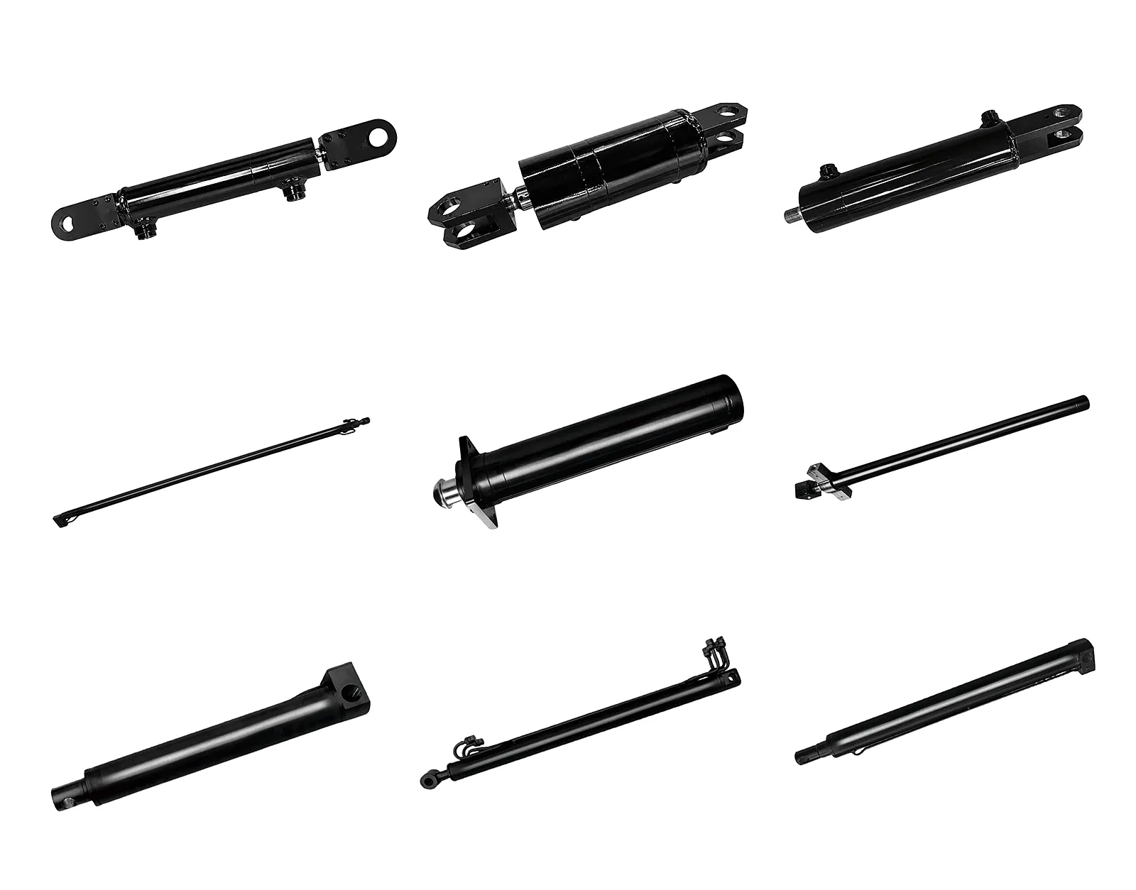
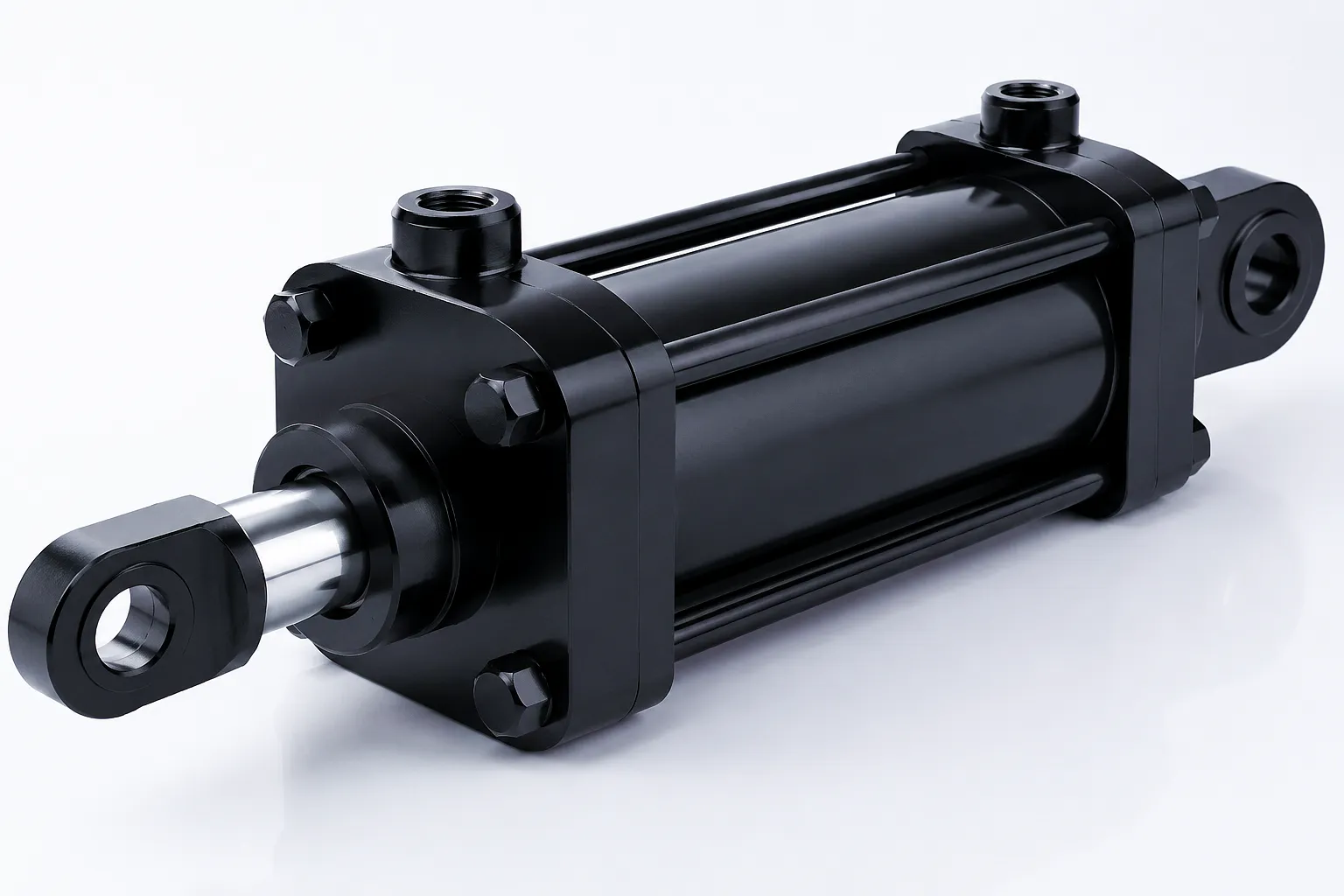
Designed for main boom angle control in aerial work platforms. Compact 555mm stroke, precision-sealed bore, pre-drilled cylinder port mounting face for direct-fit load-holding valve block installation — eliminating external hose runs between cylinder and safety valve.
Core Technical Advantages of Properly Specified Safety Valve Systems
Both device types operate without electrical power, control signals, or software. In a power-loss event — increasingly relevant for battery-electric mobile machinery now entering UK construction fleets — the safety devices remain functional because they rely purely on hydraulic force and mechanical spring resistance.
A well-specified poppet-seated POCV will hold a load indefinitely with no measurable drift — unlike a directional control valve spool, which leaks slightly around the spool-to-bore clearance. For lifting applications where even a 1mm of drift per hour is unacceptable (precision jig clamping, for instance), this performance characteristic is non-negotiable.
A properly specified counterbalance valve eliminates the “bang-bang” load movement that occurs when a spool-only circuit tries to lower a suspended load. The smooth, metered descent not only protects the load and structure from shock loading but dramatically extends hose and fitting life by eliminating the pressure spikes that accompany jerky motion.
Fitting documented, tested safety valves to your cylinder circuit significantly simplifies the risk assessment and technical file preparation required under UK Machinery Regulations 2008, PSSR 2000, and BS EN 280. Ever Power supplies full test certificates and dimensional drawings for every valve unit supplied, making compliance documentation straightforward for UK manufacturers.
Ever Power Manufacturing Capability and Custom Engineering Services
Ever Power operates precision manufacturing facilities with over two decades of experience in hydraulic cylinder and safety valve production for global B2B markets. Our engineering team handles the full design-to-delivery cycle: from initial application analysis and valve sizing calculations, through CNC machining and assembly, to factory pressure testing at up to 1.5 times working pressure, and final documentation package preparation. For UK clients, this means a single point of contact from specification to compliance paperwork — a significant advantage over assembling components from multiple generic distributors.
Customisation at Ever Power goes well beyond standard catalogue selection. Our engineers regularly produce application-specific valve blocks that integrate velocity fuse, pilot-operated check, and counterbalance functions into a single machined manifold block, bolted directly to the cylinder cap. This approach eliminates all external hose connections between cylinder and safety valve — the highest-risk point for hose-burst events — and reduces installation time on the end-user’s assembly line. Port configurations in BSP (standard for UK hydraulics), SAE O-ring, or metric thread are available, and seal material is selected based on the customer’s hydraulic fluid specification rather than a generic catalogue default.
Every steel billet, spring wire coil, and seal compound used in Ever Power safety valve production carries full mill certification and batch traceability records, retained for a minimum of ten years. For UK clients operating under PSSR 2000 and requiring Written Scheme of Examination documentation, this traceability chain is an essential part of the compliance record.
Our technical team provides free pre-sale application engineering consultations, reviewing your circuit schematic, load calculations, and duty cycle to recommend the correct valve type, set pressure, pilot ratio, and mounting arrangement. This service is available via email with typical response within 24 hours for UK enquiries.
Ever Power maintains safety valve stock programs for high-volume UK customers, with consignment stock and call-off order arrangements available for MEWP OEMs and crane manufacturers. Our documented on-time delivery rate for stocked items is above 97%, with expedited production routes available for urgent replacement requirements.
Share your circuit schematic or load data — our engineers respond within 24 hours with a detailed recommendation and price indication.
Customer Success Story: Sheffield Structural Steel Fabricator Eliminates MEWP Safety Incidents
 Steelcraft Structures Ltd operates a fleet of eight articulating boom platforms across steel erection sites in South Yorkshire and the broader Northern England region. In early 2024, during a routine LOLER (Lifting Operations and Lifting Equipment Regulations) inspection, their hydraulic engineer identified a pattern of counterbalance valve degradation on the secondary boom cylinders — valves that had been sourced from a low-cost generic distributor as service replacements eighteen months earlier. Three of the eight machines showed measurable boom drift under static load testing, which fell outside the acceptable limit for working-at-height equipment defined in their insurance provider’s inspection protocol.
After contacting Ever Power’s technical team with their existing valve cavity specifications and cylinder data sheets, a detailed application review was completed within 48 hours. The recommendation was a matched-pair counterbalance valve assembly in ductile iron with FKM seals (appropriate for the biodegradable hydraulic oil the fleet had recently adopted), set at 1.3 times the maximum calculated boom load pressure, with a pilot ratio of 4.5:1 suited to the machines’ pump pressure output during lowering operations. Ever Power produced and pressure-tested the eight valve assemblies with material certificates and individual test records for each unit, packaged with a commissioning data sheet that allowed Steelcraft’s own engineering team to complete the installations and functional tests over a single working weekend.
Post-installation LOLER testing confirmed zero static drift on all eight machines. In the twelve months following installation, the fleet recorded no hydraulic safety events and no instances of counterbalance valve-related downtime — a meaningful change from the two unplanned stoppages per quarter that had been attributed to valve-related issues in the preceding period. The business case for specifying correctly-matched safety valves rather than generic replacements was clear within a single operating season.
“The technical support before we placed the order was genuinely impressive. They reviewed our cylinder data and circuit schematic and came back with a full written recommendation — not just a catalogue part number. The valves have been on three of our machines for over a year now with no issues. We’ve standardised our entire fleet on Ever Power counterbalance valves.”
“We specified custom BSP ports and FKM seals for the bio-hydraulic fluid our client requires on a sensitive environmental site in West Yorkshire. Ever Power delivered exactly what was specified, with individual pressure test certificates for each valve and dimensional reports that went straight into our CE technical file. The price was competitive and the delivery was on schedule.”
“We’ve been buying velocity fuses and load-holding valves from Ever Power for two years now across our agricultural machinery service business in the East Midlands. Lead times are consistent, quality is clearly a step above the generic alternatives we used previously, and when we had a specification question on an unusual application, the engineering team responded with a detailed answer the same day. That kind of support keeps us coming back.”
Frequently Asked Questions — Hydraulic Safety Valves for UK Industrial Applications
How do I know what flow rate to specify for a velocity fuse on my hydraulic cylinder application in the UK?
Calculate the maximum flow rate through the cylinder port during normal operation — this is bore area multiplied by maximum piston speed. Set the velocity fuse trip point at 150–200% of this figure. If you are unsure of the piston speed, calculate it from your pump flow rate divided by the cylinder bore area. Ever Power’s technical team offers free specification support for UK clients — email [email protected] with your cylinder bore, stroke, and pump flow data.
What is the difference between a counterbalance valve and a pilot-operated check valve, and which one should I choose for my crane in Sheffield?
A pilot-operated check valve holds load with zero leakage and opens fully on pilot signal — ideal for static load holding where you need the cylinder locked in position. A counterbalance valve modulates opening proportionally to pilot pressure, providing smooth metered load lowering — the correct choice for crane circuits where the suspended load must be lowered smoothly and safely. For crane hoist circuits, counterbalance valves are the industry standard. For outrigger locking, POCVs are typically specified. Many crane hydraulic circuits use both.
How much does a custom load-holding valve block cost for a MEWP manufacturer based in Birmingham, and where can I get a quote?
Pricing for custom valve blocks depends on the number of functions integrated, body material, pressure rating, port configuration, and annual volume. For MEWP manufacturers in Birmingham and across the West Midlands, Ever Power typically provides indicative pricing within 24 hours of receiving a circuit schematic and duty cycle data. Email your enquiry to [email protected] with your cylinder specifications and target annual quantity for a fast, detailed response.
Are velocity fuses required by UK law on hydraulic cylinders used in aerial work platforms, or are they just recommended best practice?
BS EN 280, which covers mobile elevating work platforms and is the harmonised standard applied in the UK under PUWER 1998 and the UK Machinery Regulations 2008, requires positive means of load retention that does not rely solely on a directional control valve. Velocity fuses fitted at the cylinder port satisfy this requirement for burst-hose scenarios. Failure to fit them on platforms carrying persons would leave a manufacturer or operator in a difficult position under LOLER inspection, and potentially liable under HSE investigation following an incident. They are effectively mandatory for compliant MEWP design.
Which type of seal material should I specify in a load-holding valve if my machine uses biodegradable hydraulic oil on an environmentally sensitive UK site?
FKM (Viton) seals are the correct choice for load-holding valves used with biodegradable hydraulic fluids — both HETG (vegetable oil-based) and HEES (synthetic ester-based) types that are common in UK environmental applications near waterways and Sites of Special Scientific Interest. Standard NBR seals swell and degrade rapidly with synthetic ester fluids, leading to seal failure and internal leakage. Ever Power supplies FKM seal kits as standard for any valve order specifying biodegradable fluid service.
How often should velocity fuses and load-holding valves be replaced or tested on heavy plant equipment operating across UK construction sites?
There is no single mandated replacement interval that applies to all applications, but the standard industry practice for UK plant subject to LOLER and PSSR inspection is to functionally test load-holding valves and velocity fuses as part of every annual thorough examination. Functional testing should also follow any hose failure event, since a velocity fuse that trips under a burst-hose event may have its poppet seat affected by the resulting high-velocity particle contamination. Counterbalance valve performance typically degrades gradually through seat wear, making regular static drift tests (load applied, pump isolated, position monitored) the most reliable early-warning approach.
Our engineering team reviews your circuit data, calculates the correct specification, and provides detailed pricing — usually within one working day. UK orders dispatched to Birmingham, Sheffield, Manchester, Leeds, and all regions.
Editado por gzl
 Spanish
  English
  Italian
  Portuguese
  Dutch
Dutch  Swedish
  Danish
  Finnish
  Polish
  Hindi
Hindi  Kazakh
  Turkish
  Ukrainian
  Romanian
  German
  Russian
  Korean
  Japanese
  Vietnamese
  Thai
Thai  Indonesian
  Malay
Malay  French
  Greek
Greek