
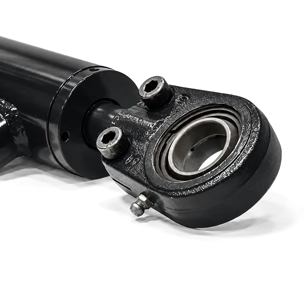
 Boom cylinders are the hydraulic heart of excavators, crane arms, reach stackers, and a broad range of lifting equipment relied upon by civil engineering contractors from Birmingham to Edinburgh. When they perform well, they are invisible — silent workhorses converting fluid pressure into precise, controlled movement. When they begin to fail, the consequences can cascade rapidly through a machine’s entire hydraulic circuit, triggering accelerated wear in pumps, valves, and hose assemblies. Understanding what deterioration actually looks like — mechanically, visually, and operationally — is the first step toward cost-effective asset management.
Visible External Oil Leakage Around the Rod Seal
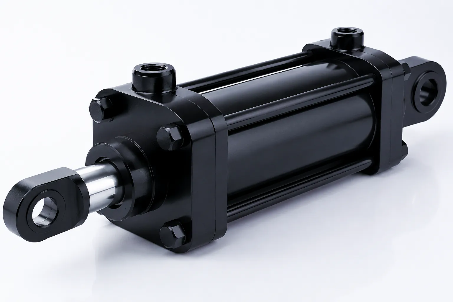 The most universally recognised symptom of a deteriorating boom cylinder is hydraulic fluid weeping or streaming from the area where the piston rod exits the cylinder barrel. Rod seals are fabricated from polyurethane, nitrile rubber, or PTFE composites and are engineered to maintain a fluid film between the seal lip and the hardened chrome rod surface — thin enough to prevent bulk leakage, thick enough to prevent dry running. Over time, exposure to particulate contamination, thermal cycling, and the mechanical fatigue of repeated stroke cycles causes the seal material to harden, crack, or extrude into the clearance gap.
On a Sheffield steel plant or a heavy civil engineering site near Manchester, oil leakage from a boom cylinder is not merely a housekeeping issue. Leaked hydraulic fluid contaminates surrounding components, creates fire risk near hot surfaces, and — critically — reduces the effective working pressure available to the cylinder. Once rod seal integrity is compromised, contamination ingress accelerates exponentially, scoring the mirror-polished rod surface and causing irreversible barrel wear.
A thin film of oil on a freshly wiped rod is borderline — worth monitoring closely. A visible drip rate, a wet stain that grows between shifts, or oil pooling beneath the machine during stationary periods are unambiguous replacement triggers. At that stage, a seal kit alone rarely resolves the underlying issue; the rod surface itself typically requires re-chroming or replacement, making a complete cylinder exchange the more economical path forward.
Loss of Holding Force and Uncontrolled Drift at Full Extension
A boom cylinder must hold a static load without measurable drift — this is non-negotiable on any lifting machine operating under the Lifting Operations and Lifting Equipment Regulations 1998 (LOLER), which applies across UK construction and quarrying sites. When a boom arm slowly sinks under load with no operator input, the most probable cause is internal bypass past a worn or damaged piston seal. Fluid is migrating from the high-pressure side of the piston to the low-pressure return side, bypassing the load-holding mechanism entirely.
Internal bypass is harder to detect than external leakage because there is no visible fluid loss — the oil simply moves from one side of the piston to the other within a sealed barrel. Operators often report the problem as the machine “feeling soft” during lifting operations, or noticing that the boom requires increasingly frequent corrections to maintain position. In Birmingham’s busy demolition sector, where excavator boom drift during a controlled demolition sequence can have serious safety consequences, this sign demands immediate investigation.
A straightforward field test involves isolating the cylinder hydraulically at full load extension and monitoring drift over a five-minute window. Any measurable drop in position under full rated load confirms piston seal failure. At this stage, the barrel bore itself should be inspected for scoring — worn piston seals dragging across a contaminated surface generate metallic debris that accelerates bore damage in a self-perpetuating cycle. Replacement of the complete cylinder unit restores designed holding performance and eliminates the compliance risk associated with drift-prone lifting equipment.
Erratic Movement, Judder, and Jerky Extension on Low-Demand Cycles
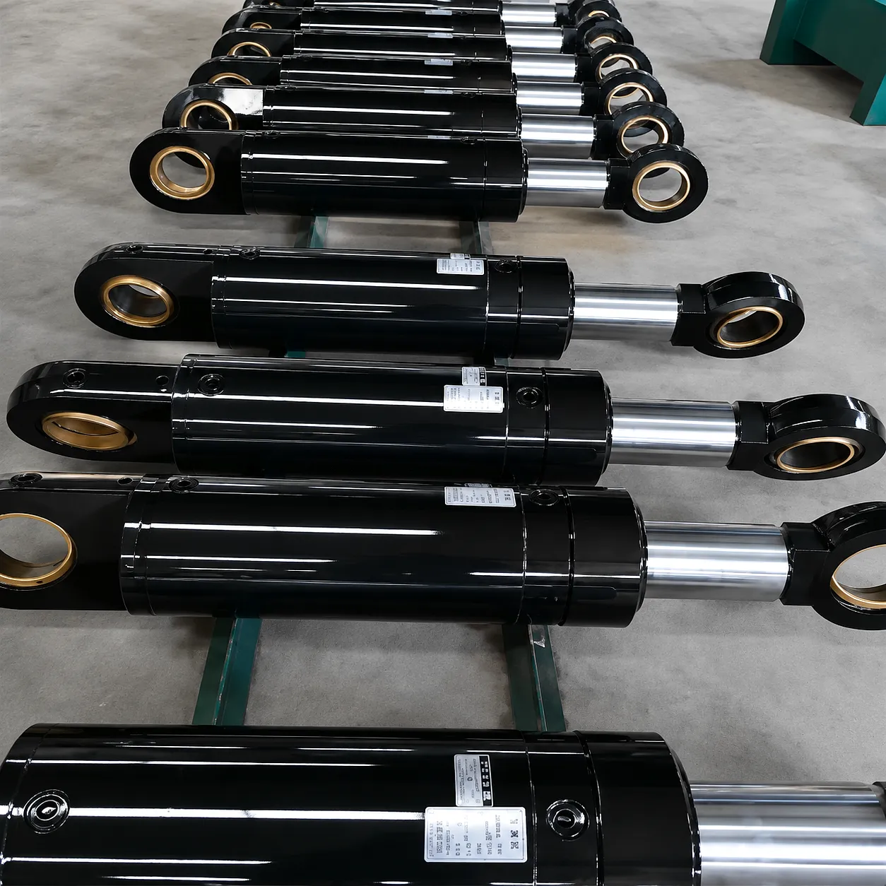 Smooth, proportional movement is the defining characteristic of a healthy hydraulic cylinder. When an operator begins to notice that the boom hesitates before responding, moves in stuttering increments rather than a fluid arc, or produces an audible thumping or clunking sensation through the operator seat, the cylinder’s internal geometry has likely been compromised. The technical term for this is stick-slip — a phenomenon where static friction momentarily exceeds the driving hydraulic force, causing the piston to stall before suddenly releasing with excess velocity.
Stick-slip arises from several concurrent failure modes: rod surface roughness caused by corrosion pitting or mechanical damage, seal material that has hardened and lost its ability to generate a stable lubricating film, or geometric distortion of the barrel bore due to side-loading beyond the cylinder’s rated specification. Northern UK construction sites — particularly groundworks contractors operating on soft clay or waterlogged ground — frequently experience side-loading beyond design limits when machines operate on significant cross-falls.
Beyond operator discomfort, stick-slip generates pressure spikes within the hydraulic circuit that exceed the steady-state design rating of connected components. Relief valves cycle unnecessarily, hose end fittings experience fatigue loads at connection points, and downstream control valves are subjected to transient flows far outside their calibration range. A cylinder displaying persistent stick-slip is actively degrading the broader hydraulic system around it, making replacement a cost-avoidance decision as much as a performance one. For operators of hydraulic rotary actuator steering cylinders and multi-axis boom systems, consistent movement quality is particularly critical to precision operation.
Chrome Rod Surface Corrosion, Pitting, and Mechanical Damage
The hydraulic cylinder rod is precision-ground and hard-chrome-plated to a surface roughness of Ra 0.2 to Ra 0.4 micrometres — a finish that allows the rod seal to generate a consistent lubrication film without either allowing bulk leakage or running dry. This surface integrity is fundamental to seal life. When the chrome layer is compromised by corrosion, mechanical impact, or abrasive contamination ingress, the seal lip encounters a surface it was never designed to accommodate, and wear rates increase by an order of magnitude.
The British climate presents specific challenges here. Machines operating on coastal civil engineering projects in areas such as the Humber Estuary or Liverpool Bay are exposed to salt-laden atmospheres that accelerate chrome corrosion, particularly where the rod is left in the extended position during idle periods. Similarly, quarrying sites in the Peak District and Scottish Highlands expose equipment to silica-rich slurry and acidic drainage water that can chemically attack chrome plating over a single winter season.
Visual inspection is the appropriate diagnostic tool here. Any visible pitting deeper than approximately 0.1 mm, rust-staining that persists after cleaning, or score marks running axially along the rod are disqualifying defects. Running a fingernail or a fine gauge probe across the rod surface will confirm whether scoring has created a detectable step — if it has, the rod surface will destroy a new seal kit within hours of installation, making complete cylinder replacement the only rational course of action.
Rod damage inspection tip: always inspect during machine warm-up when the rod has cycled several times — thermal expansion reveals pitting that may be masked when cold, and the presence of fresh fluid film makes surface damage easier to distinguish from routine surface wetness.
Structural Deformation — Barrel Bend, Weld Cracking, and Mounting Lug Wear
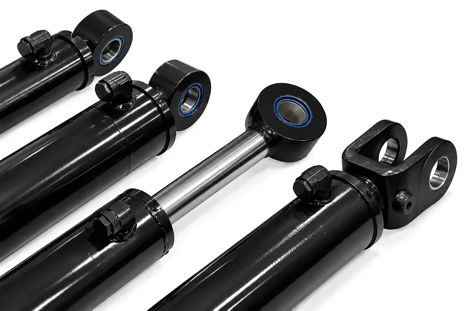 Seals and rods are wear components — they are expected to degrade over time and can, in many cases, be serviced without replacing the entire cylinder. Structural damage to the barrel, end caps, or mounting attachments is categorically different. When a cylinder barrel exhibits visible bending — even a deflection of 1 to 2 mm over a 1-metre barrel length — or when circumferential cracking appears at the barrel-to-endcap weld zone, the cylinder has experienced overload stress beyond its designed structural margin. No rebuild procedure can restore the structural integrity of a bent barrel or a cracked weld without complete remanufacture of the pressure-containing envelope.
Mounting lug wear is a related concern. Boom cylinders transmit enormous forces through trunnion-mounted or clevis-mounted attachment points, and the pin-to-bore clearance at these joints is specified tightly — typically H7/g6 tolerance on precision assemblies. As the bore wears oval and clearance increases, impact loading at direction reversal generates micro-shock events that propagate fatigue cracks from the lug root into the barrel wall. UK plant hire operations, where machines are frequently re-deployed across different applications by multiple operators, are particularly susceptible to this failure mode through accumulated abuse loading.
Inspection should include a straight-edge check across the full barrel length and close visual examination of the weld toe in good lighting with a magnifying glass — or dye-penetrant testing where a fatigue crack is suspected. Mounting lug bores should be measured with an internal bore gauge and compared against the original equipment specification. Any finding that falls outside tolerance is a replacement trigger, regardless of the condition of the seals or rod surface.
Boom Cylinder Failure Mode Diagnostic Reference
| Symptom | Root Cause | Serviceable? | Recommended Action |
|---|---|---|---|
| External rod seal leakage | Seal degradation, rod surface damage | Depends on rod condition | Inspect rod; replace cylinder if rod scored |
| Internal drift / sinking load | Piston seal bypass, bore wear | Often not — bore damage likely | Full cylinder replacement recommended |
| Stick-slip / judder | Rod roughness, hardened seals, side-loading | Possibly — early stage only | Assess rod; reseal or replace |
| Pitted / corroded rod | Chrome layer failure, chemical exposure | No — new seals will fail immediately | Replace cylinder; new rod essential |
| Barrel bend / weld crack | Overload, fatigue, abuse loading | Never — structural failure | Immediate decommission and replace |
| Worn mounting lug bores | Wear, impact loads, pin clearance growth | Minor wear: bush lining. Severe: replace | Replace cylinder if bore exceeds tolerance |
| Reduced cycle speed at rated pressure | Internal bypass, worn ports, contamination | Circuit-dependent — isolate cylinder first | Pressure / flow test; replace if confirmed |
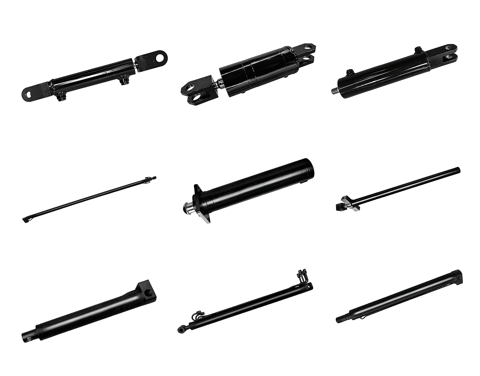
What to Do When You Identify a Failing Boom Cylinder
Step 1: Isolate and Tag
Remove the machine from active service immediately. Apply lockout-tagout procedures on the hydraulic circuit. Attempting to continue operating with a confirmed failing cylinder compounds damage to surrounding components and creates serious duty-of-care liability under UK Health and Safety at Work legislation.
Step 2: Document and Measure
Record the cylinder’s bore diameter, stroke length, rod diameter, operating pressure rating, and mounting configuration — clevis, trunnion, or flanged. Photograph all visible damage. This information is what a replacement cylinder supplier needs to confirm a compatible unit or begin a custom build to your exact specification.
Step 3: Contact a Specialist
Not all boom cylinders are stocked as off-the-shelf items — many are machine-specific and require manufacturing to specification. Work with a supplier who holds CNC turning, honing, and hard chrome plating in-house. Lead times from a well-equipped factory are significantly shorter than sourcing through an intermediary, which matters when a plant hire fleet is losing revenue daily.
Related Hydraulic Cylinder Solutions
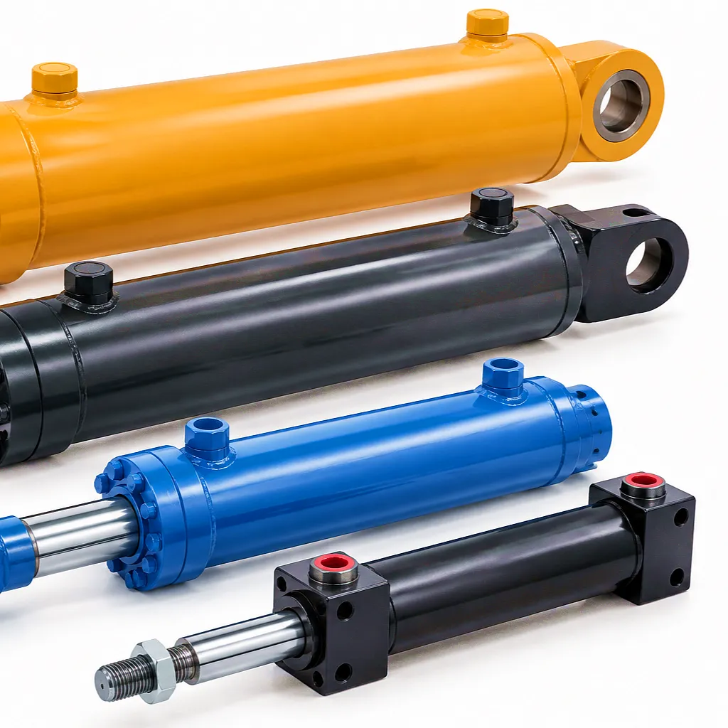
Hydraulic Rotary Actuator Steering Cylinder
Precision-engineered for steering and articulated boom applications where rotary motion and high torque are required simultaneously. Hard chrome rod, high-tensile barrel, and available with integrated position sensing for automated systems.
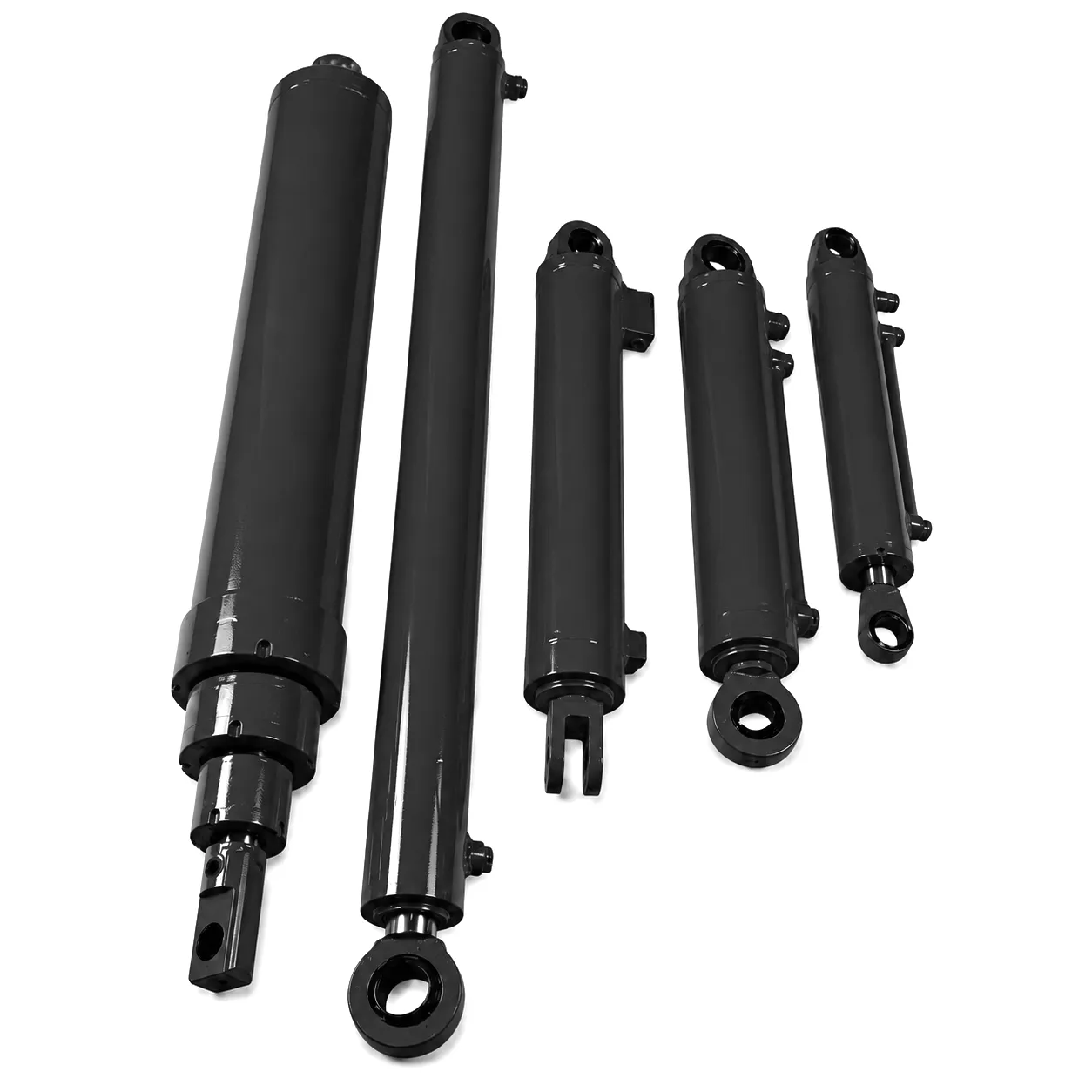
Double-Acting Forklift Tilt Cylinder
Heavy-duty tilt cylinder engineered for counterbalance forklift applications across logistics and warehousing. Dual-direction force output, compact envelope, and rated for sustained cycle frequencies typical of UK distribution centre operations.
Sheffield Structural Steel Fabrication: Replacing Four Overhead Crane Boom Cylinders Without Extended Shutdown
Broadstone Steel Fabrications, a medium-scale structural steel contractor operating from a 4,800 m² facility on the outskirts of Sheffield, contacted Ever Power in spring 2024 with an urgent brief. Their overhead travelling crane — a critical production asset used for positioning steel sections up to 12 tonnes — had developed progressive drift in the main boom raise cylinder during static holds. An inspection confirmed piston bypass with secondary scoring on the rod surface, ruling out seal-only repair. Three of the four boom cylinders on the crane showed similar wear profiles, consistent with the plant’s age and the demanding duty cycle of a fabrication environment where crane utilisation exceeds 14 hours per day.
The commercial constraint was significant: Broadstone had committed delivery dates on a major structural package for a warehouse development near Doncaster. A conventional rebuild timeline through the OEM parts route would have required a minimum six-week wait for replacement cylinders — an unacceptable production gap. Working from dimensional drawings provided by Broadstone’s maintenance team, Ever Power produced four matched replacement cylinders in 18 working days. Each unit was supplied with hard chrome rods ground to Ra 0.32 micrometres, NBR/PU composite seal packages rated for the site’s ambient temperature range, and full pressure test documentation to 1.5 times operating pressure.
Installation was completed over a single planned weekend shutdown, with the crane returning to full-rated service on the Monday. The Doncaster delivery schedule was met, and Broadstone subsequently placed a standing order with Ever Power for all future hydraulic cylinder replacements across their Sheffield facility — a decision driven by documented lead time performance and the dimensional consistency between the four units installed.
“The bore geometry on all four cylinders was within 0.02 mm of our original specification. That level of dimensional accuracy across a batch is exactly what you need when you’re dropping new units into a machine with existing bearing housings. Zero fitting issues.”
— Plant Engineer, Broadstone Steel Fabrications, Sheffield
“Eighteen days from drawing confirmation to delivery on site — that’s a number I’ll use when I’m evaluating every hydraulic supplier going forward. The pressure test certs were in order, documentation was complete, and the cylinders have been running nine months without a single fluid loss.”
— Maintenance Director, Broadstone Steel Fabrications, Sheffield
“We’d had previous experience of sourcing non-OEM cylinders that needed shimming and site-machining to fit. Ever Power’s units went straight in. The custom chrome specification they recommended for our environment has held up through a full Sheffield winter, which is the real test.”
— Operations Manager, Structural Steel Division, South Yorkshire
Ever Power Boom Cylinder Technical and Performance Specification Table
| Parameter | Standard Range | Custom / Extended | Notes |
|---|---|---|---|
| Bore Diameter | 63 mm – 320 mm | 40 mm – 500 mm | H7 tolerance standard |
| Rod Diameter | 36 mm – 220 mm | Up to 320 mm | Hard chrome 0.03–0.05 mm thick |
| Maximum Stroke | Up to 3,000 mm | Up to 6,000 mm | Slenderness ratio reviewed per application |
| Operating Pressure | Up to 250 bar | Up to 350 bar | Test pressure 1.5x working |
| Barrel Material | E355 cold-drawn seamless tube | 42CrMo4, S690QL | Material cert EN10204 3.1 |
| Rod Surface Finish | Ra 0.2 – 0.4 µm | Ra 0.1 µm available | Ground and polished post-chrome |
| Seal Material | PU / NBR composite | FKM (Viton), PTFE | Temp range -30°C to +120°C |
| Mounting Options | Clevis, flange, trunnion | Custom pin geometry | H7/g6 pin fit standard |
| Standard Lead Time | 10–18 working days | Subject to specification | Express schedule available |
अक्सर पूछे जाने वाले प्रश्नों
Answers to the questions UK plant engineers ask most often about boom cylinder replacement and sourcing.
 Hindi
Hindi  English
  Italian
  Portuguese
  Dutch
Dutch  Swedish
  Danish
  Finnish
  Polish
  Kazakh
  Turkish
  Ukrainian
  Romanian
  Spanish
  German
  Russian
  Korean
  Japanese
  Vietnamese
  Thai
Thai  Indonesian
  Malay
Malay  French
  Greek
Greek