
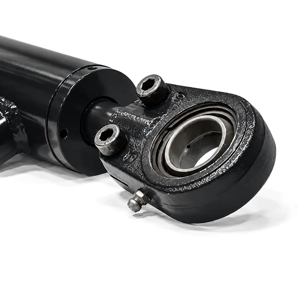
 When engineers and procurement specialists in Birmingham manufacturing plants or Sheffield steel facilities sit down to specify a hydraulic cylinder, stroke length is among the very first parameters they must define — and it is also one of the most frequently miscalculated. The stroke length of a hydraulic cylinder is not simply the visible distance a rod travels; it is an engineered dimension that determines load capacity, column strength, port sizing, installation envelope, and — critically — the safe operating envelope of the entire hydraulic circuit. A stroke measurement error of even a few millimetres can result in system failure under load, damaged seals, or complete machine downtime on a production floor where every hour of lost output carries a direct financial cost.
What Stroke Length Actually Means in Hydraulic Cylinder Design
The stroke length of a hydraulic cylinder is the total linear distance the piston rod travels between its fully retracted position and its fully extended position. It is not the same as the overall closed length of the cylinder, nor is it equivalent to the rod’s exposed length at full extension. Stroke length is a pure travel dimension — the delta between two endpoints of rod displacement — and it must be treated as an independent variable in the design equation rather than derived from the cylinder’s body length after the fact. Misinterpreting this definition is the root cause of a surprisingly large number of incorrect cylinder specifications in British industrial procurement, particularly on legacy machine retrofit projects where drawings are incomplete or measurements are taken from a worn-out original component.
In a standard double-acting hydraulic cylinder, the stroke is set by the internal geometry of the cylinder barrel and the relationship between the piston and the head. When hydraulic fluid enters the cap end port, it drives the piston — and consequently the rod — toward the rod end, extending the rod by precisely the designed stroke distance. Reversing fluid flow retracts the rod to its original position. The stroke is therefore a fixed characteristic of the manufactured cylinder, not something that varies with operating pressure or load. This is a critical distinction for system designers: if the application requires 450 mm of travel, the cylinder must have a stroke of exactly 450 mm or slightly more to accommodate alignment tolerances. Ordering a 400 mm stroke cylinder and expecting the system geometry to compensate is an engineering error that will cause hard mechanical stops and potentially catastrophic seal failure.
How to Measure Hydraulic Cylinder Stroke Length Correctly
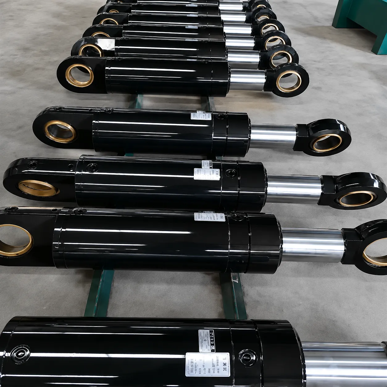
Measuring hydraulic cylinder stroke length correctly requires a structured approach that accounts for the difference between physical measurement and functional specification. There are two primary contexts in which this measurement is taken: on an existing cylinder that is being replaced or reverse-engineered, and on a new installation where the stroke must be determined from the machine’s kinematic geometry. Both contexts demand precision, but the methods differ substantially. Getting this measurement wrong on a replacement cylinder for a Birmingham automotive press line or a Sheffield forging machine can mean weeks of lead time wasted and a production line sitting idle while the correct unit is manufactured.
With the cylinder fully retracted, measure the exposed rod length from the rod seal face (gland) to the end of the rod thread or clevis connection point. Then, with the cylinder fully extended, take the same measurement. The difference between the two readings is the stroke length. On a worn cylinder, always measure from a clean reference point on the gland housing to avoid cumulative error from rod scoring or deposits.
For new installations, the stroke is derived from the kinematic travel of the mechanism the cylinder drives. Identify the two extreme positions of the mechanism (fully open/closed, raised/lowered, etc.), then calculate the corresponding linear displacement of the cylinder mounting points. Use pivot-to-pivot trigonometry if the cylinder is mounted at an angle. Add a safety margin of 5–10 mm at both ends to prevent bottoming out under thermal expansion or wear.
Never measure the closed length or overall body length of the cylinder and attempt to back-calculate the stroke without knowing the exact internal construction. Do not include mounting hardware (clevis pins, flange bolts) in stroke measurement. On telescopic cylinders, measure the stroke of each individual stage separately and sum them for total travel. Failure to distinguish between retracted length and stroke is the single most common specification error in replacement cylinder procurement throughout the UK.
Once the stroke measurement has been confirmed, it should be cross-referenced against the manufacturer’s available standard stroke increments. At Ever Power, standard stroke increments are offered in 50 mm steps for most bore sizes, with custom stroke lengths available to any dimension within the designed bore range. For retrofit projects in Leeds, Coventry, or Manchester manufacturing facilities where the original OEM cylinder is obsolete, custom stroke specification is often the only viable path to a correct replacement.
Working Principle: How Stroke Length Governs Cylinder Performance
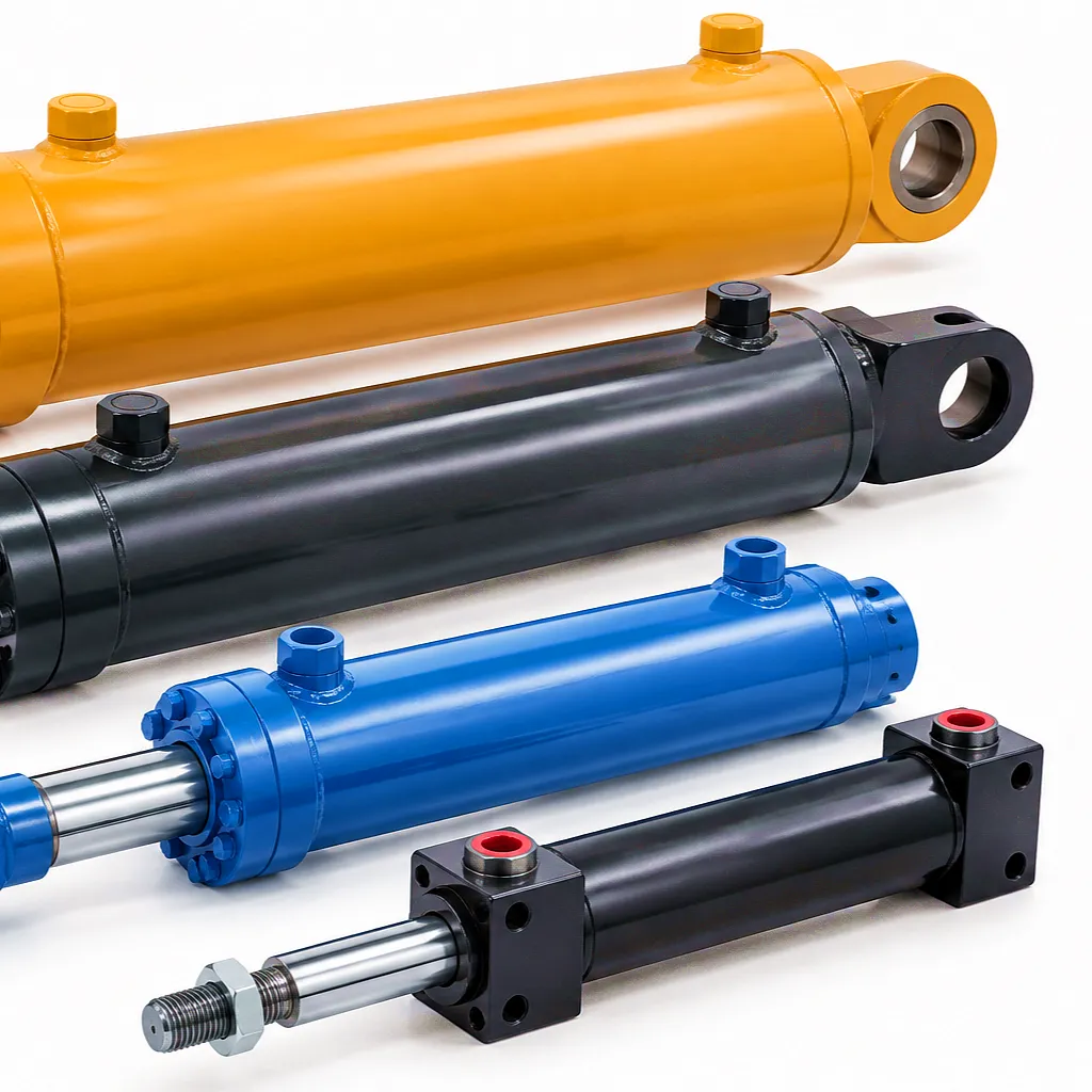
The working principle of a hydraulic cylinder is straightforward — pressurised fluid acts on the face of a piston to produce linear force — but the relationship between stroke length and cylinder performance is considerably more nuanced. Stroke length directly influences three performance-critical parameters: column strength (buckling resistance), bearing load distribution across the piston and rod guide, and volumetric flow requirements from the hydraulic power unit. Understanding these relationships is essential for any engineer specifying cylinders for long-stroke applications, which are common in UK construction equipment, agricultural machinery, and industrial press systems.
As stroke increases relative to rod diameter, the rod becomes more susceptible to Euler buckling under compressive load. The slenderness ratio (stroke ÷ rod radius of gyration) determines whether the rod must be upsized. Long-stroke cylinders used in UK mining equipment typically require chrome-plated rod diameters 20–40% larger than their bore would otherwise suggest.
The flow rate required to complete a given stroke in a specified time is a direct product of bore area and stroke length. Extending stroke from 500 mm to 1000 mm for the same bore doubles the fluid volume required per cycle. This impacts pump sizing, line sizing, and valve selection — all of which must be revisited when stroke length changes on an existing hydraulic circuit.
Longer strokes expose more rod surface area to the external environment during each extension cycle. In UK coastal or offshore applications, this increases contamination ingress risk past the rod wiper seal. Quality cylinder design mitigates this with dual-lip wipers, metallic scraper rings, and corrosion-resistant surface treatments on the chrome layer.
Core Materials Used in Hydraulic Cylinder Manufacturing
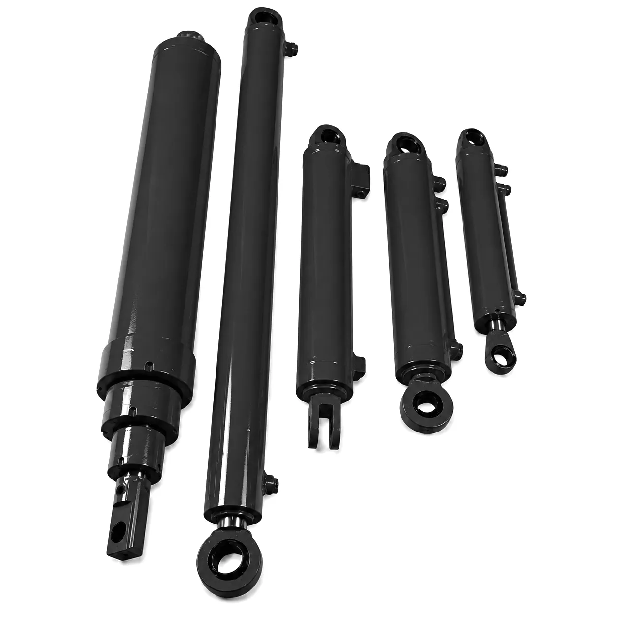
Material selection for hydraulic cylinders is inseparable from stroke specification. As stroke length increases, the mechanical stresses on the rod, barrel, and end caps change in character — and the material specification must reflect this. In Ever Power’s manufacturing facility, every hydraulic cylinder is built from certified raw materials with full traceability documentation, a standard of quality that is particularly important for UK buyers whose supply chains are subject to BS EN and CE compliance requirements. The materials used at each component level are not cosmetic choices; they are engineering decisions that determine the cylinder’s performance envelope, corrosion resistance, and total service life under the specific operating conditions of the application.
Cold-drawn seamless steel tube (ST52 / E355) with honed bore ID to Ra 0.2–0.4 µm surface finish. The tight tolerance on bore roundness — typically within ±0.02 mm — is essential for even piston seal contact across the full stroke.
C45E or 42CrMo4 alloy steel, induction hardened, ground, and hard chrome plated (minimum 20 µm). For offshore or marine UK applications, Armour-plated or HVOF-coated rods with stainless steel (316L) cores are available for extreme corrosion resistance.
Polyurethane (PU) rod seals for dynamic duty; PTFE-backed piston seals for low-friction sliding. High-temperature applications above 80°C use FKM (Viton) compound seals. Dual-lip wipers with integrated metallic scrapers protect the rod on long-stroke cycles exposed to the outdoor British climate.
EN10025 S355 structural steel for standard end caps. Ductile iron (GGG40) or forged steel for high-pressure, large-bore applications. All pressure-bearing welds are full-penetration and subject to UT/RT inspection to ISO 9013 standards.
Hydraulic Cylinder Technical & Performance Parameter Table
The following table presents the standard technical performance parameters for Ever Power hydraulic cylinders across the principal bore and stroke configuration ranges. These figures represent design values for double-acting cylinders with standard chrome-plated piston rods operating on mineral hydraulic oil at 46 cSt viscosity. Custom configurations are available outside these ranges — contact our team for engineering data sheets on non-standard specifications.
| Parametro | Small Bore (40–80 mm) | Medium Bore (80–160 mm) | Large Bore (160–320 mm) | Extra-Large (320–500 mm) |
|---|---|---|---|---|
| Intervallo di movimento | 50–1,500 mm | 50–3,000 mm | 100–5,000 mm | 100–8,000 mm |
| Operating Pressure | Up to 250 bar | Up to 300 bar | Up to 350 bar | Up to 400 bar |
| Rod Diameter Range | 22–56 mm | 56–110 mm | 110–220 mm | 220–360 mm |
| Spessore dello strato di cromo | 20–30 µm | 25–40 µm | 30–50 µm | 40–60 µm |
| Bore Tolerance (ID) | H8 (ISO 286) | H8 (ISO 286) | H8 / H9 | H8 / H9 |
| Temperatura di esercizio | da -20 °C a +80 °C | da -20 °C a +80 °C | -20°C to +100°C | -30°C to +120°C |
| Cushioning | Adjustable, one or both ends | Adjustable, one or both ends | Fixed or adjustable | Fixed or adjustable |
| Mounting Options | Clevis, flange, trunnion, foot | Clevis, flange, trunnion | Flange, trunnion, front lug | Custom flange, trunnion |
| Finitura superficiale dell'asta | Ra ≤ 0.4 µm | Ra ≤ 0.4 µm | Ra ≤ 0.3 µm | Ra ≤ 0.3 µm |
| Stroke Tolerance | +0 / -1 mm | +0 / -1 mm | +0 / -2 mm | +0 / -3 mm |
Industrial Application Scenarios: Where Stroke Specification Is Critical
Excavator boom and stick cylinders are among the most demanding long-stroke applications in any hydraulic system. Operating in the muddy, abrasive conditions of UK civil engineering sites — from HS2 groundworks to coastal flood defence projects — these cylinders must deliver strokes of 800 mm to over 2,000 mm while withstanding lateral side loads and shock loads from rock striking. Correct stroke specification here is not simply about travel distance; it determines the machine’s digging envelope, reach geometry, and lift capacity. Undersizing the stroke produces a machine that cannot excavate to design depth; oversizing it creates boom geometry that generates excessive moment loads on the cylinder rod, accelerating fatigue and bearing wear.
In the automotive pressing and metal forming industry concentrated around Birmingham and Wolverhampton, hydraulic cylinders drive die cushions, blankholder systems, and ejector mechanisms where stroke precision can be as tight as ±0.1 mm over thousands of production cycles. The stroke length here must be specified not only for the nominal die dimension but must account for tooling thermal growth, press table deflection under load, and the cumulative effect of seal wear over a multi-shift production year. Ever Power supplies custom-stroke cylinders with integrated position feedback options — linear encoders or inductive position sensors — that make the hydraulic cylinder stroke length a closed-loop, verifiable quantity rather than a fixed mechanical dimension.
Offshore supply vessels and platform service craft operating out of Aberdeen and the broader North Sea basin use hydraulic cylinders for hatch actuation, davit arms, anchor chain tensioners, and stabiliser fins. In these environments, the cylinder’s stroke length is designed to match the geometric travel of the deck equipment while the corrosion protection — stainless rod materials, PTFE-enhanced seals, and epoxy-coated barrel exteriors — must meet the far more stringent requirements of continuous saltwater exposure. Stroke lengths in this application range from 200 mm for compact hatch mechanisms to over 4,000 mm for telescopic gangway systems, and each must be specified with marine-grade documentation packages including material traceability certs and pressure test records.
From the flatlands of Lincolnshire to the rolling farmland of Yorkshire, UK agricultural machinery manufacturers rely on correctly-stroked hydraulic cylinders to drive plough lift systems, baler flywheel tensioners, and three-point linkage actuation. In this application, stroke length is often a function of the implement’s working depth range and the headland clearance required when the implement is raised. Incorrectly specified stroke produces either insufficient ground clearance on the headland (causing damage to the implement) or insufficient working depth on the field pass. Ever Power’s custom cylinder service caters specifically to UK agricultural OEMs who need small-batch production with specific pin-to-pin closed lengths that must match existing tractor mounting brackets without modification.
Sheffield’s legacy in steel and specialty metals processing continues to drive demand for heavy-duty hydraulic cylinders in rolling mill edger systems, coiler mandrels, and heat treatment furnace door mechanisms. Stroke lengths in rolling mill hydraulic cylinders are highly specific — often defined to the millimetre by the rolling mill geometry and product gauge range — and must remain stable across extreme temperature gradients as the mill transitions between hot and cold rolling schedules. High-temperature seals, thermally-stable cylinder body alloys, and precision stroke stops are all standard features on Ever Power cylinders built for UK metals processing customers, where downtime is measured in tonnes of lost product rather than hours of lost time.
Waste baling presses and industrial compactors in UK recycling facilities demand hydraulic cylinders with very long strokes — often 1,200 mm to 2,500 mm — combined with very high operating pressures to achieve the compaction ratios required by modern recycling specifications. In these machines, stroke length determines the bale density and chamber fill factor, which directly translates to operational efficiency and revenue per bale. Ever Power manufactures hydraulic cylinders for UK waste management OEMs with oversized rod diameters, high-strength barrel alloys, and hardened tie-rod configurations that resist the eccentric loading inherent in baling press operation, where the load is rarely perfectly centred on the cylinder axis.
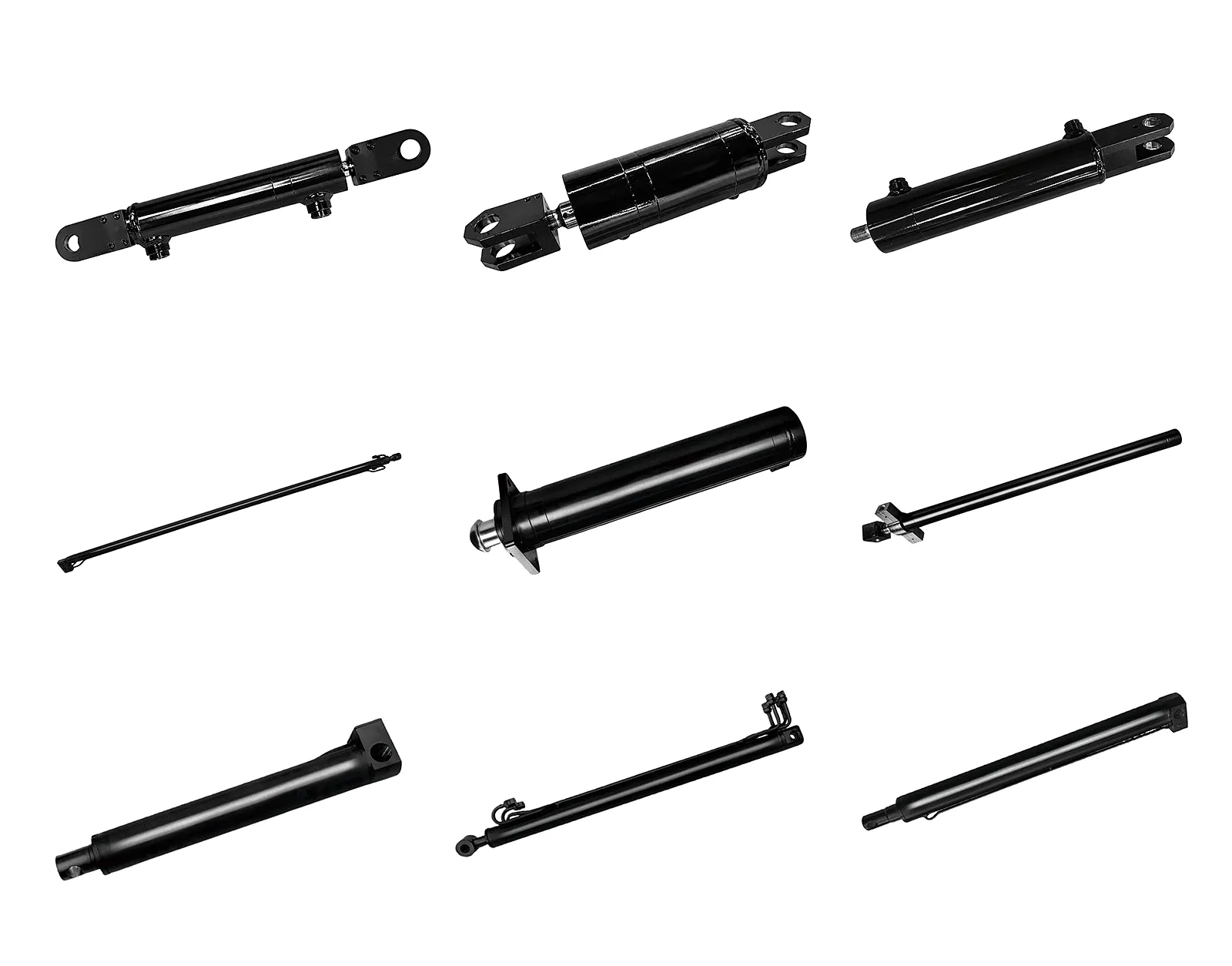
Ever Power Hydraulic Cylinder Product Range — Custom stroke, bore, and mounting configurations available
Core Technical Advantages of Correctly Specified Hydraulic Cylinders
Correctly specified stroke with mechanical end cushioning prevents hard-stop impact, protecting seals, piston, and the driven mechanism from shock loading that degrades system life exponentially.
A stroke-matched rod diameter selection ensures the slenderness ratio stays within Euler’s safe zone for the operating load, eliminating lateral deflection and the catastrophic seal failure associated with a buckled rod in a production hydraulic circuit.
A cylinder with correctly specified stroke matches fluid volume demand precisely to the application travel, avoiding pump oversizing and the associated energy waste — a consideration increasingly important under UK energy efficiency regulations in manufacturing.
When stroke is matched to the application envelope, seals operate within their designed contact pressure range for the full stroke. Oversized cylinders cause seals to operate at reduced pressure on a portion of the stroke, promoting micro-leakage channels and dramatically reducing seal change intervals.
Precisely specified stroke avoids the use of unnecessarily long cylinders — a common outcome of “overspecifying for safety” — which adds weight, increases closed-length packaging constraints, and creates interference risks with adjacent machine structures in tight industrial installations.
A correctly dimensioned stroke creates a clean linear displacement envelope for integrated position transducers (LVDTs, magnetostrictive sensors) used in servo-controlled or proportionally-controlled hydraulic circuits, enabling accurate position feedback with no dead-band at the ends of travel.
Ever Power: Precision Manufacture & Customisation Capability
ISO 9001 Certified | Custom Stroke & Bore | Global Supply
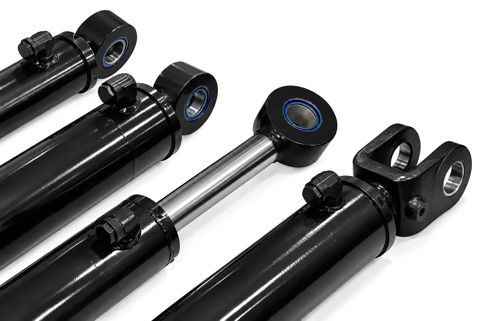
Ever Power operates one of the region’s most technically capable hydraulic cylinder manufacturing facilities, built specifically around the needs of industrial B2B customers who cannot accept standard catalogue products for their applications. Our machine shop capability spans CNC-honed barrel production from 40 mm to 500 mm bore, deep-hole drilling to 8,000 mm barrel length, precision rod grinding to Ra 0.2 µm, and hard chrome plating lines that accommodate rod diameters from 22 mm to over 360 mm. Every cylinder leaving our facility undergoes a full pressure test at 1.5 times the rated working pressure and a stroke function test before despatch, with all test data provided as a traceable quality record.
For UK customers, Ever Power’s customisation service is structured around the realities of British procurement: minimum order quantities starting at a single unit for prototype and replacement work, DDP delivery to UK ports (typically Felixstowe, Tilbury, or Southampton) with all customs and compliance documentation handled, and a technical engineering team that can work from incomplete drawings, worn original parts, or system layout sketches to develop a correct custom specification. Our typical lead time for custom-stroke hydraulic cylinders is 15–25 working days from confirmed order, with expedited 7–10 working day options available for urgent maintenance replacements on production-critical equipment.
Leeds Recycling Plant: Solving a Long-Stroke Baling Press Failure
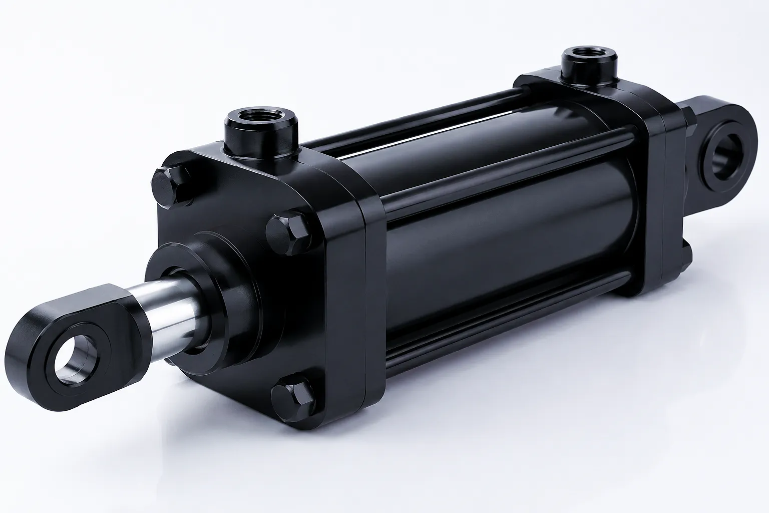
A specialist waste management and materials recovery company operating a major recycling facility in Leeds faced an acute production crisis when the primary main ram cylinder of their channel baler failed during a peak operating period. The machine — a large-throughput baler processing mixed commercial and industrial waste — relied on a 160 mm bore cilindro idraulico with a 1,750 mm stroke as its main compression ram. The original cylinder, sourced from the baler’s European OEM, had a quoted lead time of 11 weeks ex-factory — an impossible wait for a facility processing several hundred tonnes of material per week with a gate commitment to their local authority waste collection contracts.
The company’s engineering manager contacted Ever Power through the boom-cylinders.com technical enquiry channel with photographs of the failed cylinder, a hand-measured set of dimensions, and the hydraulic circuit pressure specification from the machine’s original commissioning documentation. Ever Power’s engineering team cross-referenced the measured stroke with the machine’s schematic, confirmed the bore and stroke dimensions, selected an appropriate rod diameter (100 mm, 42CrMo4, hard chrome plated) for the 1,750 mm compression stroke under 280 bar operating pressure, and issued a full manufacturing specification within 24 hours of the initial enquiry. The replacement cylinder was built, pressure-tested at 420 bar, and despatched DDP to the Leeds facility within 9 working days. The engineering manager supervised the installation on day 11 after the original failure — a total downtime of less than two weeks compared to the 11-week OEM lead time they had been quoted.
The successful outcome was a direct result of accurate stroke measurement combined with Ever Power’s ability to manufacture to custom dimensions without minimum order penalties. The replacement cylinder has since completed over 180,000 baling cycles without any seal replacement, significantly outperforming the original OEM component that had required seal changes every 60,000–70,000 cycles due to a rod surface finish specification that was below the application’s requirements.
“The stroke tolerance on the replacement cylinder was spot on — it went straight into the machine without any shimming or adjustment on the clevis pins. Ever Power clearly understood that the 1,750 mm figure was a functional dimension, not an approximation. We’ve had zero issues since installation.”
“What impressed me most was how quickly their team identified the correct rod diameter for the stroke length. Our in-house team had assumed the OEM-spec rod was the only option. Ever Power specified a slightly larger rod and explained exactly why — it’s made a tangible difference to cycle life. The chrome finish quality is genuinely excellent.”
“We now use Ever Power as our primary hydraulic cylinder supplier for all baler replacement work across our Northern England sites. The 9-working-day turnaround on a custom 1,750 mm stroke cylinder is something no UK stocking distributor can match on a non-standard dimension. Delivery to our Leeds site was seamless — the crate arrived undamaged and perfectly packed.”
Frequently Asked Questions About Hydraulic Cylinder Stroke Length
Ever Power’s engineering team is ready to review your stroke, bore, and pressure requirements and return a full quotation within 24 hours. UK DDP delivery available.
 Italian
  English
  Portuguese
  Dutch
Dutch  Swedish
  Danish
  Finnish
  Polish
  Hindi
Hindi  Kazakh
  Turkish
  Ukrainian
  Romanian
  Spanish
  German
  Russian
  Korean
  Japanese
  Vietnamese
  Thai
Thai  Indonesian
  Malay
Malay  French
  Greek
Greek