
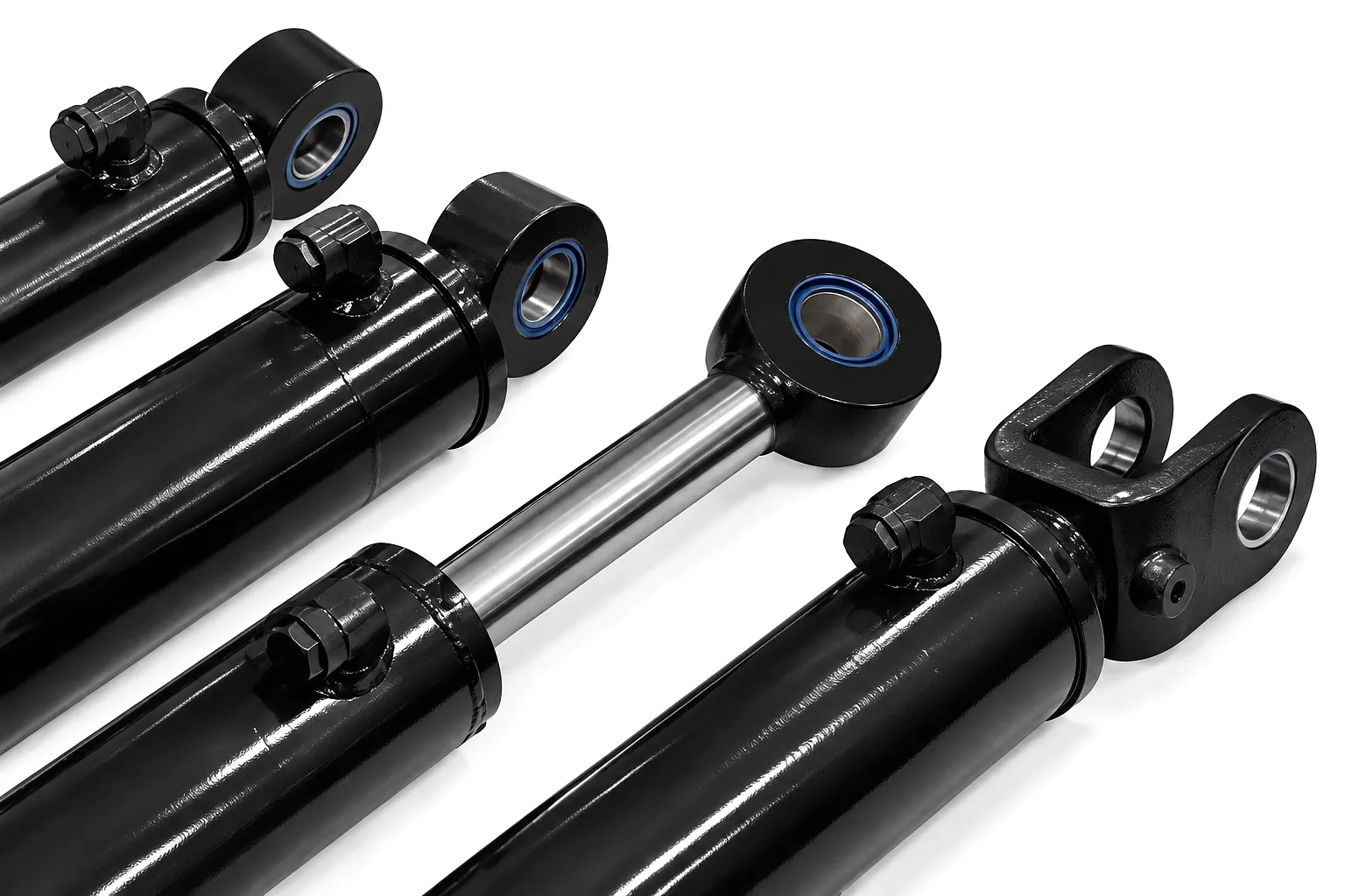
 Choosing between a hydraulic cylinder and a pneumatic cylinder is one of the most consequential decisions in any mechanical actuation project. Both devices convert energy into linear mechanical force, yet their operating principles, output characteristics, and suitable environments differ so significantly that selecting the wrong type can compromise safety, efficiency, and operational budget simultaneously. For UK manufacturers and plant engineers — from the steel fabricators of Sheffield to the agricultural equipment producers of Lincolnshire — understanding these distinctions at a granular technical level is not merely academic; it directly determines whether a machine performs reliably under production conditions or fails prematurely.
Hydraulic cylinders use pressurised incompressible fluid — typically mineral oil — to generate force, while pneumatic cylinders rely on compressed air. This seemingly simple difference cascades into profound performance gaps in terms of force output, positional precision, environmental tolerance, and running cost. The following deep-dive explores every dimension of that gap, grounded in measurable engineering data and real-world UK industrial applications.
How Each Cylinder Type Works: The Governing Principles
Cilindro idraulico
A hydraulic cylinder operates on Pascal’s Law: pressure applied to a confined incompressible fluid transmits equally in all directions. A hydraulic pump — driven by an electric motor or a PTO shaft — pressurises oil, which is then routed through control valves into the cylinder bore. The pressurised oil acts on the piston face, generating a push or pull force proportional to the product of pressure and piston area. Because oil is essentially incompressible under practical working pressures (up to 350 bar in high-performance industrial systems), the piston position is determined almost exclusively by fluid volume, giving exceptional positional control. The fluid itself also serves as a lubricant, extending component life significantly in continuous-duty industrial environments such as Birmingham’s metal pressing plants or the heavy-fabrication workshops lining the banks of the Humber.
Pneumatic Cylinder
A pneumatic cylinder uses compressed air — typically at 4–10 bar — to drive a piston inside a cylindrical barrel. Because air is compressible, the behaviour is fundamentally different from hydraulics. When compressed air enters one chamber, it expands against the piston, and the piston moves until the air pressure equilibrates with the opposing load. This compressibility introduces a natural cushioning effect that makes pneumatics well-suited to rapid, repetitive, light-duty strokes. Air supply systems are simpler to maintain, leaks do not contaminate the working environment (a critical advantage in food processing facilities in West Yorkshire or pharmaceutical packaging lines in Hertfordshire), and system infrastructure is less capital-intensive. However, pneumatic cylinders rarely exceed 25 kN of force at standard supply pressures, which limits their application in heavy industrial scenarios.
Force Output and Speed: Where the Real Differences Live
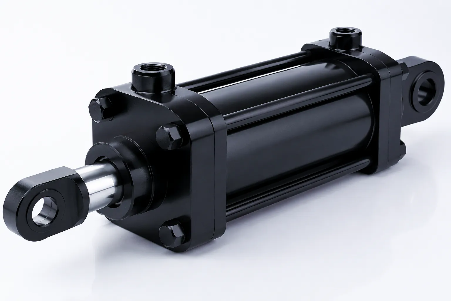
The force equation for any linear actuator is straightforward: Force (F) = Pressure (P) × Piston Area (A). The critical variable is the pressure range achievable by each technology. Hydraulic systems operate at pressures between 50 and 350 bar (5 to 35 MPa), while pneumatic systems are practically confined to 4–10 bar. This pressure differential means hydraulic cylinders can deliver forces in the range of 5 kN to several thousand kN from physically compact bores, while pneumatic cylinders with equivalent bore diameters are limited to a fraction of that output. For a 100mm bore cylinder at 200 bar hydraulic pressure, the theoretical push force is approximately 157 kN — a figure that would require a pneumatic cylinder with a bore exceeding 1,000mm at 10 bar to replicate, which is clearly impractical. This is why every heavy press, mining longwall shearer, and dock crane in the UK’s industrial belt relies on hydraulic actuation rather than pneumatic power.
Speed characteristics present a more nuanced picture. Pneumatic cylinders extend and retract very rapidly — often at 0.5 to 1 m/s without auxiliary speed controls — because expanding air discharges quickly and flow resistance is low at typical bore sizes. Hydraulic cylinders can also achieve high speeds, but control is inherently smoother, and positioning can be held mid-stroke with a closed valve, something impossible with standard pneumatic circuits. For UK automotive pressing lines in the West Midlands or stamping operations in Coventry, this difference between controlled deceleration and abrupt air exhaust affects both component quality and tooling longevity.
Technical Performance Parameters: Side-by-Side Specification Table
The table below consolidates the most critical engineering parameters across both actuator categories, enabling direct comparison at the specification stage of a project. Data reflects standard industrial grades as supplied to UK OEM customers and plant operators.
| Parametro | Cilindro idraulico | Pneumatic Cylinder |
|---|---|---|
| Operating Pressure | 50 – 350 bar | 4 – 10 bar |
| Max Force Output | 5 kN – >5,000 kN | 0.1 kN – 25 kN |
| Typical Bore Diameter | 25 – 500 mm | 8 – 320 mm |
| Stroke Speed | 0.01 – 0.5 m/s (controlled) | 0.1 – 1.5 m/s |
| Positional Accuracy | ±0.01 mm (with servo valve) | ±0.1 – ±2 mm |
| Body Material | Honed steel tube, cast iron, stainless steel | Aluminium alloy, stainless, polymer |
| Seal Materials | Polyurethane, NBR, PTFE, Viton | NBR, EPDM, silicone, PTFE |
| Temperatura di esercizio | -40°C to +120°C (fluid dependent) | da -20 °C a +80 °C |
| Leak Contamination Risk | Oil leak possible — environmental risk | Air leak — no contamination |
| Energy Efficiency | High (70–85% system efficiency) | Low (20–35% system efficiency) |
| Maintenance Interval | Every 2,000–5,000 hours | Every 5,000–10,000 cycles |
Core Materials in Hydraulic and Pneumatic Cylinder Construction
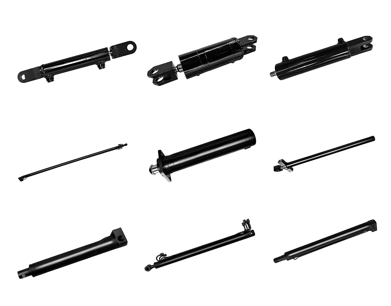
Cilindro
Hydraulic cylinders use precision-honed cold-drawn steel tubes (typically St52 or E355 grade) with internal surface roughness of Ra 0.2–0.4 µm. This finish is critical: it determines seal life and leakage performance. For corrosive or high-cycle marine environments — such as offshore supply vessels operating out of Aberdeen — 316L stainless or chrome-plated bore tubes are specified. Pneumatic barrels, facing far lower burst pressures, frequently use aluminium alloy extrusions (6063-T5 or 6061-T6), which reduce weight by 65% versus steel and lower cycle inertia.
Asta del pistone
Hydraulic piston rods are manufactured from high-tensile alloy steel (CK45 or 42CrMo4) with hard chrome plating of 20–35 µm thickness, achieving a surface hardness of approximately 850 HV. This treatment resists side-loading, corrosion, and seal wear simultaneously. Premium installations in Sheffield’s precision-engineering sector may specify induction-hardened rods with ceramic plasma coatings for extreme abrasion resistance. Pneumatic rod specifications are less demanding — carbon steel or anodised aluminium typically suffice for the lower pressure regime.
Sistema di tenuta
Seals are the performance-defining components of both actuator types. Hydraulic cylinders employ multi-element seal packages: a primary Polyurethane (PU) rod seal, a secondary wiper seal to exclude contaminants, a static O-ring for end cap sealing, and guide rings in PTFE-bronze composite to manage side loading. For high-temperature duty (above 80°C) in UK foundry or glass furnace environments, Viton (FKM) elastomers are specified. Pneumatic seals use NBR or EPDM for standard duty, with silicone grades deployed in temperature extremes.
Industrial Application Scenarios: Where Each Cylinder Excels
💧 Hydraulic Cylinder Applications
Where massive force, sustained load-holding, or precision control under high pressure is mandatory.
Excavator boom and bucket cylinders, crane slewing mechanisms, bridge-bearing lift systems, and tunnelling shield drives represent the backbone of hydraulic applications in UK construction. Crossrail and HS2 tunnelling operations required hydraulic thrust cylinders capable of pushing TBM sections with forces exceeding 100 MN. For agricultural machinery — from combine harvesters operating across the Yorkshire Wolds to telehandlers serving Herefordshire farms — hydraulic cylinders provide the robust, overload-tolerant actuation that pneumatics simply cannot match under field conditions. Hydraulic Cylinders For Combine Harvester Machine exemplify this demanding duty cycle.
Hydraulic presses in Birmingham’s metalworking district deliver consistent compressive forces from 50 tonnes to 5,000 tonnes for forging, deep drawing, and powder compaction. The incompressible fluid medium means force is applied gradually and consistently, which is critical for dimensional repeatability in aerospace-grade parts manufacturing. Sheffield’s tool-steel producers rely on hydraulic cylinder-driven press frames to maintain tolerances of ±0.05 mm across forming strokes exceeding 500 mm in length — a precision level completely outside the capability envelope of pneumatic actuation.
Telescopic hydraulic cylinders are the preferred actuator for vehicle lifts, scissor platforms, and elevated work platforms across UK warehousing and logistics infrastructure. The load-holding capability under a closed valve — with zero energy input — makes hydraulics inherently safer and more energy-efficient for elevated static loads. Custom Double Acting Telescopic Hydraulic Cylinders For Lifting Platform are engineered for precisely this category of duty, providing multistage extension with controlled retraction under load.
💨 Pneumatic Cylinder Applications
Where high cycle rates, clean operation, low infrastructure cost, or food/pharma regulatory compliance takes priority.
Pneumatic cylinders dominate food processing lines because air leaks are harmless from a product contamination perspective, whereas any hydraulic fluid intrusion would constitute a serious food safety incident. In West Yorkshire’s extensive food manufacturing sector — covering everything from baked goods in Bradford to confectionery in Halifax — pneumatic cylinders drive filling valves, packaging conveyors, reject flaps, and portion control mechanisms at cycle rates of 60–200 strokes per minute. Food-grade air cylinders with stainless steel bodies and FDA-compliant EPDM seals are specified for washdown environments where daily high-pressure cleaning is standard practice.
Light assembly operations in electronics, consumer goods, and automotive components leverage pneumatic cylinders for clamping, pick-and-place, part orientation, and small component pressing tasks. The inherent speed and compliance of compressed air makes over-force protection a natural feature — if a component jams, the cylinder stalls without generating destructive loads. In Swindon’s extensive automotive supply chain and Coventry’s electronics sub-assembly workshops, pneumatic grippers and rodless cylinders form the backbone of flexible manufacturing cells capable of processing hundreds of components per hour.
Cleanroom-rated pneumatic cylinders are the only practical choice in pharmaceutical tableting, capsule filling, and blister packaging environments where ISO Class 5 or Class 7 contamination standards apply. Stevenage and Macclesfield’s pharmaceutical clusters, home to major global API manufacturers, rely extensively on cleanroom-compliant pneumatic actuators with stainless housings, electropolished internal surfaces, and zero-lubricant seals. The UK’s MHRA regulatory framework requires full traceability and validated cleaning procedures that are far simpler to achieve with air-operated equipment than with oil-based hydraulic systems.
Hydraulic Cylinder Product Advantages: Why Force-Critical Applications Choose Hydraulics
Superior Force Density
Hydraulic actuators generate orders of magnitude more force per unit cross-sectional area than any pneumatic alternative. This power density advantage makes them the only viable solution for applications requiring sustained loads above 30 kN, enabling compact designs in space-constrained machine frames.
Precision Positioning
Paired with servo-proportional valves and linear transducers, hydraulic cylinders achieve positioning repeatability of ±0.01 mm — a capability demanded by die-casting machines, injection moulding presses, and CNC bending centres throughout the UK’s precision engineering sectors in Coventry and Derby.
Static Load Holding
A pressurised hydraulic cylinder with its supply valve closed holds its load indefinitely without continuous energy input. This intrinsic lock-in-place capability is a fundamental safety feature in lifting equipment, clamping fixtures, and any application where power loss must not result in uncontrolled movement — a requirement directly addressed in UK PSSR 2000 regulations.
Energy Efficiency at Scale
Modern variable-displacement hydraulic pump systems — increasingly prevalent in UK manufacturing following energy-cost pressures post-2021 — consume energy only when work is actually performed. System efficiency of 70–85% compares favourably to pneumatic systems where compressor losses and air leakage typically result in only 20–35% of input electrical energy reaching the point of work.
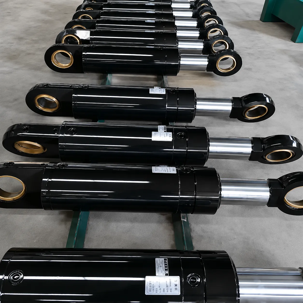 Ever Power operates a vertically integrated manufacturing facility equipped with CNC honing machines capable of achieving bore tolerances of H7/H8 (±5 µm), automated chroming lines with precision thickness control to ±2 µm, and a hydraulic test bench capable of validating cylinders at up to 420 bar proof pressure with full leakage rate documentation. This infrastructure enables Ever Power to move from design specification to first article inspection in as little as 10 working days for standard configurations, with full custom designs engineered and manufactured within 25 working days — a lead time that UK plant engineers and procurement managers routinely compare favourably against European competitors.
Customer Success Story: Replacing Pneumatic Actuators in a Sheffield Steel Fabrication Plant
Heavy Steel Fabrication
Resolved 2024
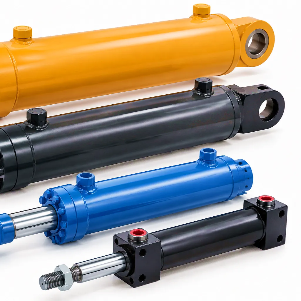 A mid-sized structural steel fabricator based in the Lower Don Valley, Sheffield — producing beams, columns, and weldments for the construction sector across the Midlands and North of England — had been operating a beam-clamping and positioning system using 63mm bore pneumatic cylinders at 8 bar supply pressure. The setup generated a maximum clamping force of approximately 2.5 kN, which proved insufficient for holding heavy I-beams (up to 200 kg per section) during robotic welding, resulting in positional drift of 2–4mm per pass that caused weld joint failures and required costly rework amounting to roughly £180,000 annually.
The plant’s engineering team contacted Ever Power to specify a replacement system. After an on-site technical review, Ever Power proposed four custom 80mm bore, 350mm stroke double-acting hydraulic cylinders at 160 bar working pressure, generating 80 kN clamping force — a 32-fold improvement over the previous pneumatic arrangement. The cylinders were specified with integrated pilot-operated check valves to maintain clamping position even under pump shutdown, chrome-plated CK45 rods, and compact flange-mount housings engineered to retrofit directly into the existing clamping frame without structural modification.
Delivered within 18 working days of order confirmation, the four cylinders were commissioned over a single weekend shutdown. Post-installation measurement confirmed positional repeatability of ±0.15 mm across the full welding cycle — well within the ±0.5 mm tolerance required by the robotic welding programme. The annual rework cost was eliminated in the first quarter of operation, delivering a full return on the hardware and installation investment within six months. The plant subsequently extended the same hydraulic clamping solution to two additional fabrication bays.
What Our UK Customers Say
“The clamping force improvement was night and day. We went from fighting positional drift every shift to not thinking about it at all. Ever Power’s engineering team understood our problem immediately and gave us a solution that fitted without any fabrication changes on our end. The lead time was the best we’ve seen from any supplier, domestic or overseas.”
“We specified custom telescopic cylinders for a lifting platform retrofit on a distribution centre project in Birmingham. Ever Power provided full CAD drawings within 48 hours of receiving our brief, and the finished cylinders matched every dimension precisely. Their technical support answered questions about seal selection for our biodegradable fluid within hours. An excellent supplier for bespoke hydraulic work.”
“We’ve trialled four different hydraulic cylinder suppliers over the past three years for our combine harvester attachments. Ever Power’s product quality is consistently the best — the rod surface finish is immaculate, the seal kits are properly labelled and packed, and we’ve had zero warranty claims across 18 months of field use. Their willingness to accommodate non-standard stroke lengths at no surcharge is genuinely unusual in this market.”
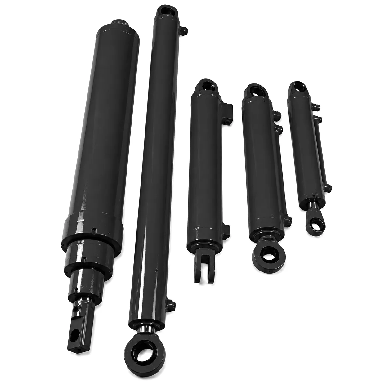
Looking for custom telescopic cylinder solutions for lifting applications? Ever Power engineers are ready to review your specification.
Domande frequenti
Ready to Specify Your Hydraulic Cylinder?
Whether you’re replacing pneumatic actuators, upgrading an existing hydraulic system, or specifying cylinders for a new OEM design, Ever Power’s engineering team is ready to assist. Send your drawings, dimensions, or application brief directly.
[email protected] · Ever Power Group · Response within 24 hours
modifica a cura di gzl
 Italian
  English
  Portuguese
  Dutch
Dutch  Swedish
  Danish
  Finnish
  Polish
  Hindi
Hindi  Kazakh
  Turkish
  Ukrainian
  Romanian
  Spanish
  German
  Russian
  Korean
  Japanese
  Vietnamese
  Thai
Thai  Indonesian
  Malay
Malay  French
  Greek
Greek