
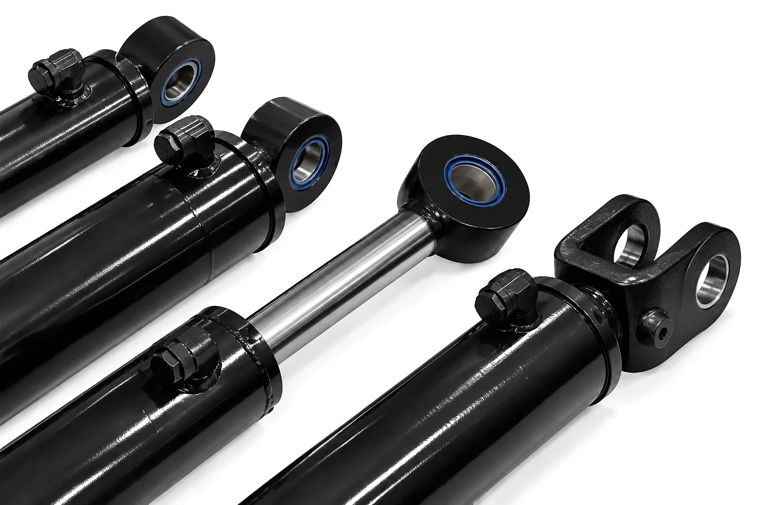
 When engineers and procurement managers in Sheffield’s fabrication yards, Birmingham’s automotive plants, or Leeds’s hydraulic service centres specify a cylinder, three numbers define almost everything about how that component will perform in service: the rod diameter, the stroke, and the collapsed length. These three dimensions govern load capacity, travel distance, and the physical space the cylinder occupies within a machine frame. Getting them right from the outset avoids costly modifications, downtime, and the frustration of a unit that simply does not fit the envelope. Across UK heavy industry, where tolerances on bespoke plant are tight and lead times matter, a solid grasp of hydraulic cylinder dimensions is not optional — it is foundational engineering knowledge that separates a well-specified machine from a maintenance liability.
Need Custom Hydraulic Cylinders for Your UK Operation?
Tell us your rod diameter, stroke, and collapsed length — we’ll engineer the rest.
Rod Diameter Explained: The Load-Bearing Backbone of Every Hydraulic Cylinder
Core Specification | Structural Integrity
The rod diameter — sometimes referred to as the piston rod diameter or rod OD — is the external diameter of the solid steel shaft that projects from the cylinder barrel and transmits force to the load. It is, in many respects, the structural spine of the assembly. Too slender a rod and the cylinder faces the engineering problem of Euler column buckling: under compressive axial load, the rod deflects laterally rather than pushing cleanly, and failure can be sudden and catastrophic. Too large a rod relative to the bore, and the effective annular area on the rod side of the piston is reduced, altering the extend/retract force balance and increasing the system’s overall mass without proportional gains in performance. British standard engineering practice typically aligns rod diameter selection to a recognised ratio against bore diameter, often ranging from 0.5:1 for lighter applications up to 0.7:1 or greater where high compressive loads, long strokes, or side-loading conditions are present.
For UK manufacturers sourcing cylinders for press tooling in Wolverhampton’s metalworking sector, or for agricultural attachments in Yorkshire’s farm machinery market, the rod diameter calculation must also account for the chrome plating thickness applied to the rod surface. A hard chrome layer of 0.025–0.05 mm per side is typical on industrial-grade rods, enhancing corrosion resistance and providing the hardness (typically HRC 60–65) necessary for seal longevity. Some high-specification applications, particularly offshore-adjacent work common in Aberdeen and the northeast, specify alternative coatings such as electroless nickel or HVOF thermal spray chrome alternatives that meet more stringent environmental standards. The nominal diameter quoted in any specification sheet refers to the finished, plated diameter, and this figure must match the bore of the rod seals precisely.
Stroke Length: Defining Travel, Reach, and Machine Architecture
Travel Specification | Machine Integration
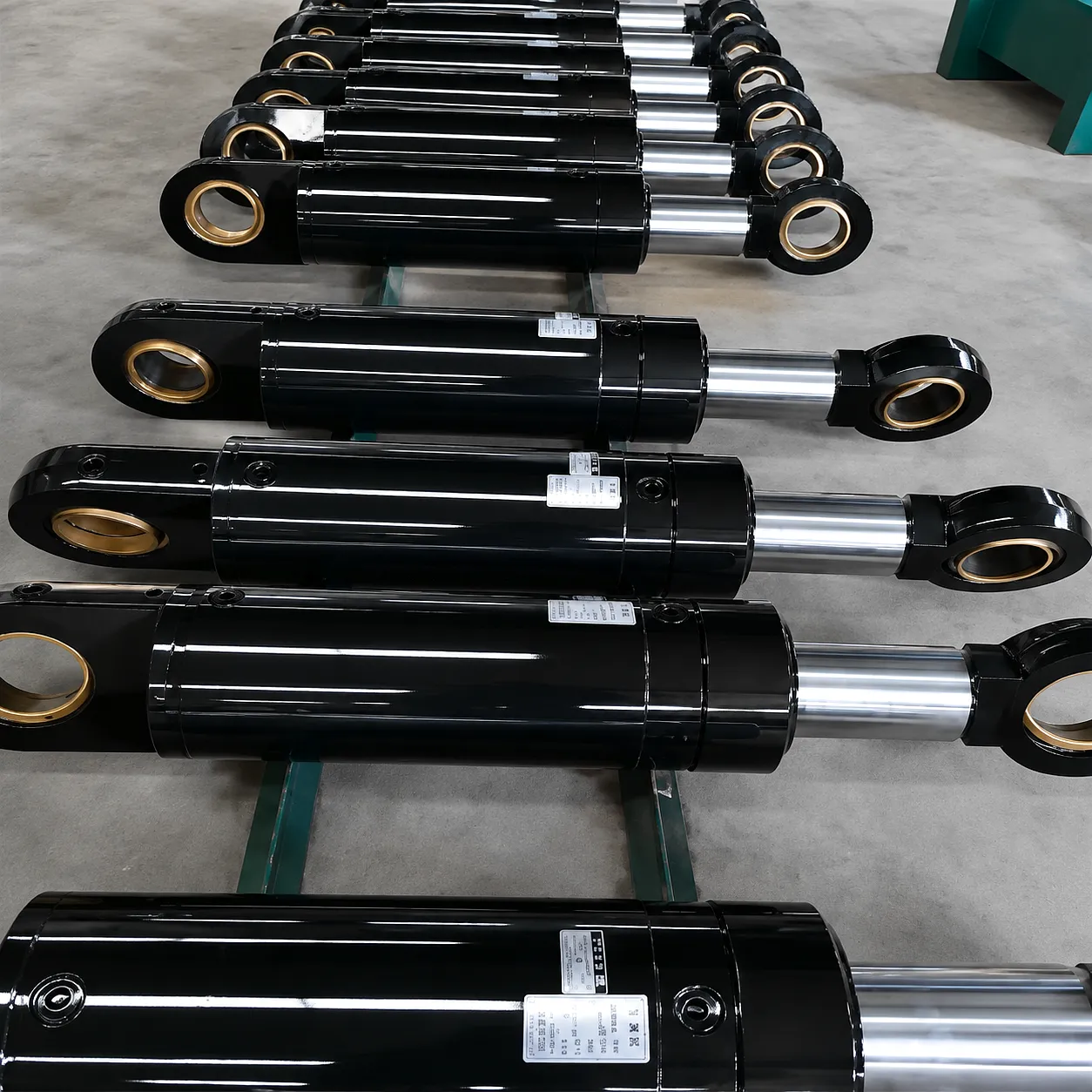
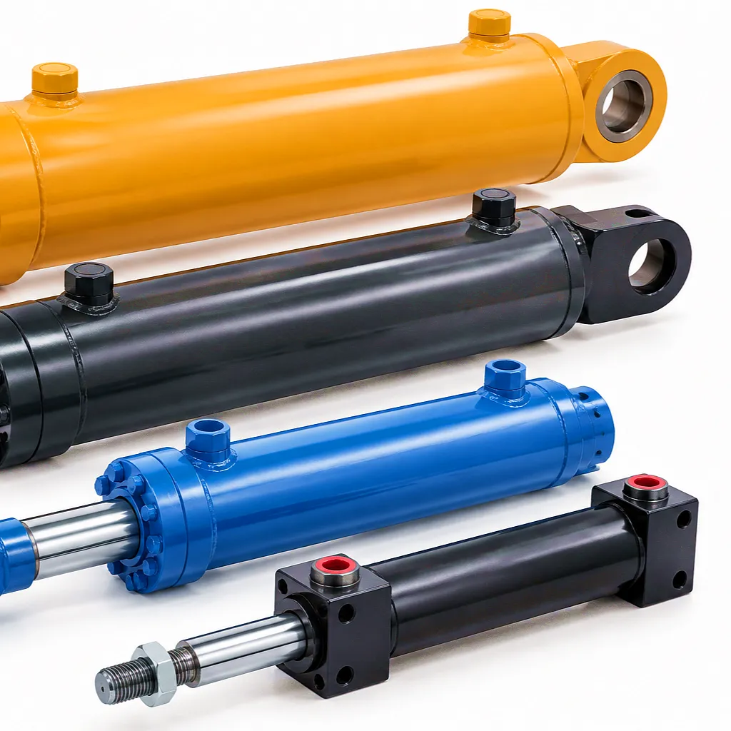
Stroke length is the total linear distance the piston rod travels between its fully retracted and fully extended positions. It defines the operational reach of the cylinder — how far it can move a load, how wide a gate or hatch it can open, how high a platform it can lift. For UK buyers specifying hydraulic cylinders for construction equipment on infrastructure projects or for waste management plant in Coventry’s industrial zones, stroke length must be calculated against the machine’s actual mechanical travel requirement, typically with a small engineering margin to avoid the cylinder bottoming out or reaching the end of its stroke under dynamic loading conditions.
One of the less-discussed consequences of long stroke lengths is their effect on rod buckling susceptibility. As stroke increases, the unsupported length of the rod when extended grows correspondingly, and the critical buckling load drops in proportion to the square of that unsupported length — a relationship described by Euler’s formula for slender columns. This is why long-stroke cylinders routinely require a larger rod diameter than a short-stroke unit of identical bore would suggest. Engineers working on telescopic lifting platforms common in Midlands warehouse automation, or on the long-travel tilting mechanisms of heavy vehicle transporters, must perform explicit buckling calculations rather than relying solely on bore-based force charts.
Stroke length also influences the seal wear pattern over the cylinder’s service life. A cylinder that consistently operates over its full stroke subjects seals to the maximum possible dynamic sliding distance per cycle, accelerating wear. Applications in which the cylinder only rarely travels its full stroke — such as an overload-relief ram — may use a generous stroke with minimal wear consequences. Conversely, cylinders in high-cycle press or injection moulding applications typical of East Midlands plastics manufacturing require seal specifications calibrated for millions of complete stroke cycles, which often means a lower surface roughness on the rod and barrel bore, and seal materials selected for heat and chemical resistance alongside mechanical durability.
Featured Product
Silinder Hidraulik Teleskopik Bertindak Dua Kali Tersuai Untuk Platform Pengangkat
Multi-stage stroke solution for high-reach lifting applications — ideal for warehouse platforms and vehicle hoists across the UK.
Collapsed Length: The Envelope Constraint That Decides Whether Your Cylinder Fits
Installation Dimension | Machine Frame Compatibility
Collapsed length — also called closed length or retracted length — is the total length of the cylinder assembly measured from mounting-to-mounting when the rod is fully retracted. It represents the minimum physical space the cylinder occupies within the machine frame, and for many retrofit or OEM applications, it is the most constraining single dimension in the specification. A cylinder with the correct bore, rod diameter, and stroke is useless if its collapsed length exceeds the available mounting envelope. This is a problem that surfaces repeatedly in UK plant replacement programmes, where engineers attempt to upgrade an existing machine with a higher-performance cylinder without altering the surrounding structure.
The collapsed length of a standard tie-rod or welded hydraulic cylinder is determined primarily by four factors: the stroke length, the piston thickness, the end cap and gland thickness at each end, and the length of the rod gland assembly. In a welded body cylinder, the design can often be optimised to minimise the collapsed length for a given stroke — an important consideration in compact mobile plant such as the skid steers and telehandlers used extensively on UK construction sites in Manchester and Glasgow. By reducing the internal dead length — the sum of non-stroke-contributing internal dimensions — a competent manufacturer can often shave 30–60 mm from the collapsed length without altering bore, rod diameter, or stroke, simply through careful end cap and gland geometry.
Telescopic cylinders, by contrast, achieve large total strokes within a comparatively short collapsed length by nesting multiple stages within one another. A two-stage telescopic unit might deliver 1,200 mm of stroke from a collapsed length of only 700 mm — a ratio impossible with a single-stage design. This dimensional efficiency makes telescopic cylinders the dominant choice in tipper trucks, refuse vehicles, and agricultural trailers throughout rural and urban UK logistics networks. Understanding the relationship between stage count, individual stage stroke, and collapsed length is essential for anyone designing or specifying these products, and it is a discipline that demands manufacturer-level expertise to execute reliably.
How Rod Diameter, Stroke, and Collapsed Length Interact in Engineering Design
Engineering Integration | Specification Balance
The three primary dimensional parameters of any hydraulic cylinder — rod diameter, stroke, and collapsed length — do not exist independently of one another. They form an interconnected engineering system in which a change to any one parameter propagates through the others and through downstream performance characteristics. Understanding these interdependencies is what separates a genuinely well-engineered specification from a table of numbers assembled without mechanical context.
Consider a hydraulic cylinder specified for a bespoke press brake in a Sheffield steel-processing facility. The required extend force dictates the bore. The bore suggests a minimum rod diameter to avoid buckling under the compressive press load. The stroke is set by the die gap requirement. Taken together, these determine a minimum collapsed length, which must then fit within the press frame. If the collapsed length exceeds the frame clearance, the engineer faces a set of options: reduce the rod gland length, switch to a welded body instead of a tie-rod design to save a few centimetres, consider a shorter-stroke design with a mechanical linkage to amplify travel, or — in extreme cases — revisit the frame design. Each of these decisions has cost and lead time implications that must be balanced against the original machine requirements.
The stroke-to-rod-diameter ratio also influences the cylinder’s natural frequency and its tendency to oscillate under dynamic loading. In servo-hydraulic systems used in test rigs and simulation platforms — a growing sector in UK automotive engineering around Warwickshire and Oxfordshire — these dynamic properties are as important as the static force capacity. A cylinder with a high stroke-to-rod-diameter ratio behaves differently under rapid directional changes, and the control system must be tuned to match. This intersection of mechanical dimension and dynamic behaviour is one reason why hydraulic cylinder suppliers who understand their customers’ full application context deliver better outcomes than those who simply quote standard catalogue numbers.
3
Critical dimensional parameters that define every hydraulic cylinder’s compatibility and performance
Technical Performance and Dimensional Parameter Reference Table
Standard Industrial Specifications | Ever Power Capability Range
| Parameter | Standard Range | Custom Range | Notes |
|---|---|---|---|
| Rod Diameter | 25 – 200 mm | Up to 450 mm | Chrome-plated, hardened; tolerance h6/f7 |
| Bore Diameter | 40 – 320 mm | Up to 600 mm | Honed bore; Ra 0.4 typical |
| Panjang Strok | 50 – 3,000 mm | Up to 8,000 mm (multi-stage) | Subject to buckling check; long strokes may need stop tubes |
| Collapsed Length | Stroke + 150–300 mm | Optimised per application | Welded body allows tighter dead-length ratios |
| Operating Pressure | Up to 250 bar | Up to 500 bar | High-pressure seals; pressure-tested at 1.5x rated |
| Rod Material | CK45 carbon steel | 42CrMo4 alloy, stainless 316 | Surface hardness HRC 58–65 after chrome |
| Bahan Tong | ST52 seamless tube | E355 / S355 / duplex stainless | Honed internally; weld-certified for pressure |
| Sealing System | Polyurethane + PTFE | Viton, NBR, HNBR, low-temp options | Matched to fluid type and temperature range |
| Temperature Range | -20°C to +80°C | -40°C to +150°C | Special seals required outside standard range |
| Rod Overhang / Buckling | Per Euler buckling calculation | Stop tube integration available | Safety factor 3.5:1 minimum recommended |
Material Science Behind Hydraulic Cylinder Rods and Barrels
Metallurgy | Surface Engineering | Longevity
Piston Rod Material Selection
The choice of rod material has profound implications for a hydraulic cylinder’s service life, its resistance to environmental degradation, and its performance under dynamic loading. The most widely used material for hydraulic cylinder rods in UK industrial applications is CK45 carbon steel, a medium-carbon grade with a carbon content of approximately 0.45% that responds well to induction hardening and offers a good combination of tensile strength, machinability, and cost-effectiveness. After turning and precision grinding to the required diameter, the rod is typically hard chrome plated to a thickness of 0.02–0.05 mm, which deposits a surface with Vickers hardness in the range of 800–1,000 HV and a surface roughness of Ra 0.2–0.4 microns — the ideal combination for seal compatibility and corrosion resistance in typical industrial environments. For applications in coastal regions of the UK, such as port equipment in Felixstowe or offshore-support facilities in Aberdeen, corrosion resistance demands shift beyond what standard chrome plating reliably delivers, and materials such as 316L stainless steel or specialist composite rods with HVOF tungsten carbide coatings come into consideration.
Barrel and Tube Material
The cylinder barrel is most commonly manufactured from ST52 or E355 seamless cold-drawn steel tube — a grade offering a minimum yield strength of 355 MPa and excellent weldability for end cap and port fitting connections. After rough machining, the bore is precision-honed to achieve the surface finish and dimensional accuracy required for reliable piston seal performance. Internal bore roughness is typically specified to Ra 0.4–0.8 microns, with roundness and straightness tolerances in the H7 or H8 tolerance band. For medium to heavy-duty applications common throughout the UK’s construction equipment sector and the agricultural machinery belt stretching from Lincolnshire into East Yorkshire, this combination of materials provides a durable, predictable, and cost-effective platform. The barrel wall thickness is calculated to withstand the design pressure with a safety factor — typically 3:1 or greater in compliance with BSEN standards — and serves as the primary structural member tying the end caps together under hydraulic load.
Industrial Application Scenarios: Where Cylinder Dimensions Are Mission-Critical
UK & Global Industrial Applications
Construction Plant — Birmingham & Midlands Infrastructure
Excavators, crawler cranes, and piling rigs operating on Birmingham’s HS2 construction corridor demand hydraulic cylinders where the collapsed length fits within tight boom and stick geometries, while the rod diameter must resist the lateral loading imposed by hard ground conditions. Stroke lengths are matched precisely to the designed bucket or blade travel. Dimensional miscalculation at the specification stage translates directly into failed fitting or poor machine performance on-site — which on a time-critical infrastructure programme carries substantial financial penalty.
Agricultural Machinery — Combine Harvesters and Crop Headers
Agricultural hydraulic cylinders face a demanding combination of long stroke requirements for header height adjustment and tight collapsed length constraints imposed by the header geometry and transport height regulations on UK public roads. Combine harvesters working the harvest circuits of Cambridgeshire and Norfolk rely on cylinders with carefully optimised dimensional profiles to achieve the required working height range without exceeding legal transport dimensions. Seal packages must tolerate dust, crop debris, and temperature cycling from cold mornings to hot afternoon operation.
Vehicle Lifting Platforms — Logistics and Warehouse Operations
Scissor lifts, tail lifts, and mobile elevated work platforms deployed in UK warehousing and distribution — particularly in logistics hubs around Daventry, Milton Keynes, and East Midlands Gateway — rely on telescopic hydraulic cylinder designs to achieve platform heights of 8–14 metres from a compact retracted profile. The stroke-to-collapsed-length efficiency of multi-stage telescopic cylinders is central to the usable load capacity and vehicle overhanging limitations in these applications, and specifying the correct rod diameter at each telescopic stage prevents inter-stage buckling failures under uneven loading.
Steel and Metal Processing — Sheffield and Rotherham Forges
Sheffield’s long-established steel and special metals sector places some of the most demanding requirements on hydraulic cylinder dimensions of any UK industry. Forging presses, rolling mills, and manipulators operate with cylinders under extreme compressive loads at relatively short strokes but with very large rod diameters to manage the forces involved — in some cases exceeding 300 mm rod OD for master press cylinders. Collapsed length constraints are less critical in dedicated press frames but the sealing and rod surface specifications must withstand scale, heat, and metallic contamination in the press environment. Material traceability to BSEN or customer-specific standards is a non-negotiable requirement for tier-one Sheffield supply chain work.
How to Calculate and Specify Hydraulic Cylinder Dimensions for Your Application
Engineering Process | Procurement Guidance
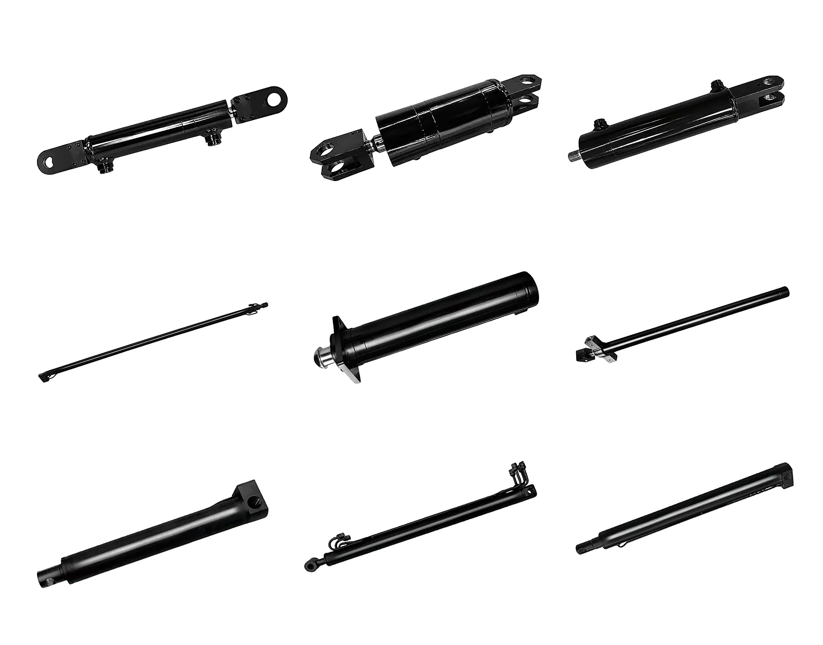
Specifying a hydraulic cylinder begins with defining the force requirement. The extend force in a double-acting cylinder equals system pressure multiplied by the piston bore area: F = P × (pi/4) × D². With force and pressure established, bore diameter follows directly. From bore, rod diameter is selected to provide adequate buckling resistance over the required stroke — this requires either Euler column calculation or reference to the manufacturer’s rod-selection charts, which vary by mounting configuration and whether the cylinder operates in tension or compression.
Stroke length is an application-driven parameter — it must come from the machine’s mechanical travel requirement — but the engineer must then verify that the selected rod diameter is adequate for the full extended length. The ratio of free (unsupported) extended length to rod diameter should typically remain below values that would bring the cylinder close to its Euler critical load at the applied force. For pin-pin mountings, the critical buckling force is expressed as: Fc = pi² × E × I / Le², where E is the modulus of elasticity of the rod steel (approximately 210 GPa), I is the second moment of area of the rod cross-section (pi × d⁴ / 64), and Le is the effective (free) length. A safety factor of at least 3.5 is standard UK practice for mobile plant and at least 4.0 for static installations under shock loading.
Collapsed length is then determined by the manufacturer’s design — typically stroke plus a dead length of 150–300 mm for standard industrial cylinders — and must be checked against the available mounting envelope in the machine. If the standard collapsed length does not fit, the options include specifying a short-gland design, a welded-body cylinder rather than a flanged tie-rod type, or a custom end cap configuration. UK buyers working with Ever Power benefit from the ability to specify any of these configurations with custom collapsed lengths to as little as ±5 mm of the required dimension.
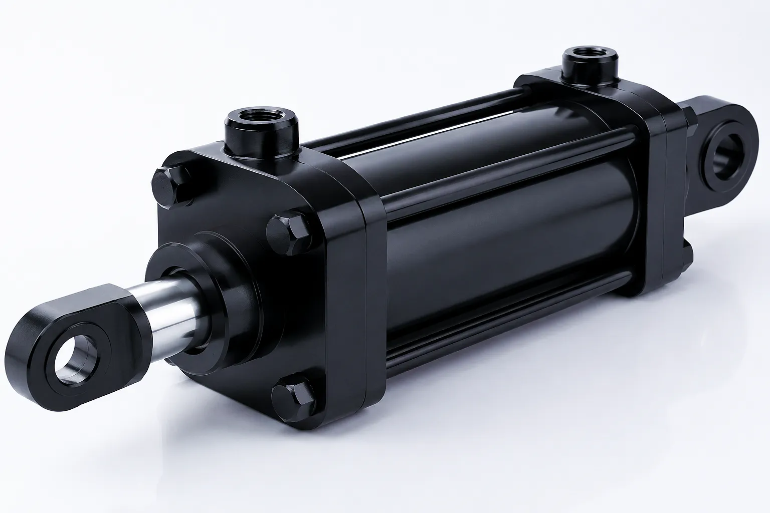
Customer Success Story: Sheffield Steel Forge Achieves Precision Fit with Custom Cylinder Dimensions
Case Study | UK Heavy Industry
Customer Reviews
★★★★★
“The collapsed length matched our press frame to within 2 mm on first delivery. We had been burned by loose tolerances from a previous supplier and Ever Power completely restored our confidence in sourced replacements. Rod surface quality was excellent and seals bedded in with no leaks.”
— Works Engineer, Alloy Steel Forging Facility, Sheffield
★★★★★
“We specified telescopic cylinders for a custom lifting platform project in Birmingham — non-standard stroke lengths and a tight collapsed length that ruled out all catalogue products we could find in the UK. Ever Power designed a bespoke two-stage unit that met every dimension and delivered on time. Communication from the technical team was clear and knowledgeable.”
— Senior Hydraulic Design Engineer, Plant Manufacturer, Birmingham
★★★★★
“Rod diameter selection advice from Ever Power saved us from an under-specified cylinder on a long-stroke agricultural attachment. Their engineer spotted the buckling risk in our original calculation and recommended the correct rod size immediately. That kind of pre-sale technical input is genuinely rare and we have since placed multiple orders for our range of implement cylinders.”
— Procurement Manager, Agricultural Equipment Manufacturer, Lincolnshire
Core Technical Advantages of Precision-Dimensioned Hydraulic Cylinders
Product Performance Benefits
Dimensional Consistency Reduces Assembly Time
When rod diameter, stroke, and collapsed length are manufactured to tolerance rather than to a nominal figure with unchecked variation, cylinders fit their mounting envelopes on first installation without rework. This is particularly valuable in production-line OEM assembly environments where each additional fitting hour has a calculable cost impact. Ever Power’s CMM-verified delivery documentation provides the dimensional assurance that UK OEM customers need for their own quality records.
Optimised Rod Diameter Extends Seal Life
A rod diameter matched correctly to the bore and stroke — neither over-specified (adding weight and cost unnecessarily) nor under-specified (increasing deflection under side loading) — produces a dynamically stable cylinder that operates with minimal rod flexion as it extends and retracts. Rod flexion is a primary cause of accelerated seal wear; reducing it through correct dimensional specification extends seal service intervals and reduces maintenance costs over the cylinder’s operational life.
Collapsed Length Accuracy Enables Drop-In Replacement
When a cylinder’s collapsed length is manufactured to within ±5 mm of specification, it becomes a genuine drop-in replacement for field failures. This capability shortens downtime from days to hours in breakdown situations, and in sectors like UK aggregate quarrying, steel processing, or commercial vehicle maintenance where unplanned downtime has an hourly financial cost, the value of precise collapsed-length manufacturing is immediately apparent and justifies choosing a supplier capable of delivering it.
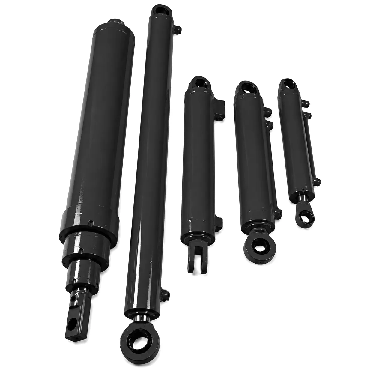
Heavy Duty Range
Heavy Duty Hydraulic Cylinder Manufacturer — Single Acting Cylinders
Purpose-built for high-force single-direction applications — available with custom rod diameters, strokes, and collapsed lengths for UK industrial plant.
Frequently Asked Questions — Hydraulic Cylinder Dimensions
Technical Q&A | UK Industry
Ever Power | Boom Cylinders
Ready to Specify Your Hydraulic Cylinder?
Send us your rod diameter, stroke, and collapsed length requirements. UK industrial buyers receive a technical response within 24 hours.
✓ Bespoke Stroke Lengths
✓ Optimised Collapsed Length
✓ UK Industrial Supply
✓ EN 10204 3.1 Certification
suntingan oleh gzl
 Malay
Malay  English
  Italian
  Portuguese
  Dutch
Dutch  Swedish
  Danish
  Finnish
  Polish
  Hindi
Hindi  Kazakh
  Turkish
  Ukrainian
  Romanian
  Spanish
  German
  Russian
  Korean
  Japanese
  Vietnamese
  Thai
Thai  Indonesian
  French
  Greek
Greek