
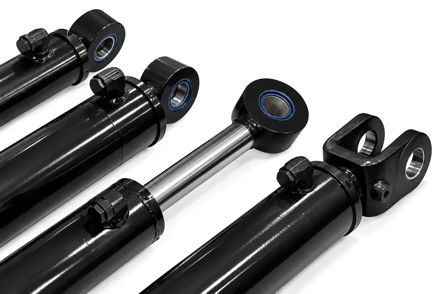
What Are Side Loads and Why Do They Matter?
A side load is any force acting perpendicular — or at an angle — to the central axis of a hydraulic cylinder’s piston rod. When a cylinder is designed, its internal geometry assumes that thrust and return forces travel in a perfectly straight line along that axis. The moment the mounted load deviates from this ideal path, the rod begins to experience bending stress at the gland and guide bearing. These lateral loads are transmitted through the piston rod, into the rod seal, across the bronze guide bush, and ultimately into the cylinder tube wall. The result is uneven seal compression on one side, accelerated metal-to-metal contact at the piston lands, and premature gland seal failure — all while the cylinder may still appear functional from the outside. Many UK engineers working with hydraulic cylinders in mobile plant equipment have noted that rods often exhibit a characteristic polishing pattern on one face, which is the physical signature of persistent misalignment.
The mechanical consequence escalates non-linearly. Research from hydraulic system reliability studies indicates that a rod subjected to a persistent lateral force equal to just 5% of its rated axial load can see its seal life reduced by 40–60%. At 10% lateral deviation, seal life may drop to less than a third of specification. In real-world plant environments — particularly in the agricultural machinery belts of Lincolnshire, the offshore support equipment yards of Aberdeen, and the heavy-press facilities of Coventry — this translates directly to costly reactive maintenance cycles. Furthermore, misaligned hydraulic cylinders introduce erratic system pressure spikes as the rod tries to self-correct, which stresses the hydraulic pump and directional control valves throughout the circuit. Recognising side load conditions early and correcting them through proper alignment practice is therefore not just a matter of cylinder longevity — it is a system-level reliability concern.
Root Causes of Cylinder Misalignment in Industrial Applications
Structural Deflection
Machine frames and fabricated brackets undergo elastic deflection under load. A mounting lug that sits perfectly true under no-load conditions may shift several millimetres when the machine is working at full capacity. In the hydraulic press lines common to West Midlands tooling operations, this movement introduces repeating angular misalignment at the cylinder pin joints with every press cycle — creating a fatigue pattern that compounds over thousands of operational hours.
Incorrect Mounting Geometry
This is the single most frequent cause encountered during initial installation. When a cylinder’s trunnion, flange, or clevis mount is fixed to a structure without ensuring that the rod centreline and the load centreline are co-linear throughout the full stroke, side loads are built into the design from day one. This is especially common on retrofit installations where an existing hydraulic cylinder replaces a pneumatic actuator on a different centreline datum.
Thermal Expansion
Industrial processes involving elevated temperatures — casting lines in Rotherham, vulcanising presses in Yorkshire, or die-casting operations in Birmingham — cause the machine frame to expand at different rates depending on material and section thickness. A cylinder aligned precisely at ambient temperature may develop a side-loading condition once the machine reaches its operating temperature of 80–120°C. Thermal alignment surveys conducted at both cold and hot states are essential in these environments.
Worn Pivot Pins and Bushes
Over time, the clevis pins, spherical bearings, and bronze bushings at both the cap end and rod end of a cylinder accumulate clearance through wear. What begins as a 0.05 mm manufacturing tolerance can grow to 0.5–1.5 mm of play in heavily cycled systems. This slop in the pivot assembly translates directly into angular misalignment under directional load reversals, and it is particularly acute in hydraulic cylinders fitted to excavator booms and agricultural baler arms that cycle many thousands of times each season.
Related Product
Heavy Duty Single Acting Cylinders — Built for Demanding UK Plant Environments
For applications where mounting geometry constraints make full double-acting circuits impractical, Ever Power’s heavy duty single acting cylinder range offers reinforced guide bush sections and extended gland land lengths that dramatically improve resistance to side loading. These cylinders are specified by maintenance engineers seeking to extend service intervals in press, clamping, and lifting applications throughout the UK.
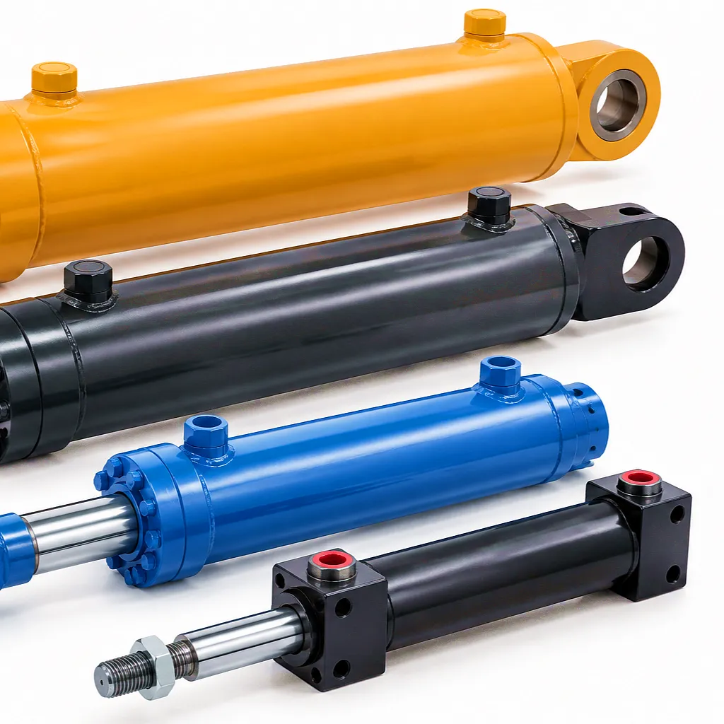
Core Alignment Principles: The Engineering Framework
Getting hydraulic cylinder alignment right requires applying a systematic framework rather than relying on a visual approximation. The principles below represent accepted industry practice, refined over decades of hydraulic engineering and validated in demanding industrial environments from the North Sea energy sector to the precision manufacturers of the Thames Valley. Three governing concepts underpin every sound alignment approach: axial co-linearity, articulation accommodation, and deflection compensation.
Axial Co-linearity
The rod centreline must remain coincident with the load centreline through the entire working stroke — from fully retracted to fully extended. Any angular offset between these two axes creates a moment force at the gland. The maximum allowable angular offset for a standard hydraulic cylinder with rubber seals is typically 0.05°–0.1°, though this tightens considerably for longer stroke cylinders operating at pressures above 250 bar. Achieving axial co-linearity requires careful use of precision levels, dial gauges, and where budgets permit, laser alignment systems, particularly for fixed-flange mounted cylinders where no articulation is built into the mounting arrangement.
Articulation Accommodation
In applications where the load path changes during the working stroke — such as on lifting arms, rear linkages of tractors operating in the agricultural regions of Norfolk and Cambridgeshire, or the outrigger systems of mobile cranes across the UK — the cylinder must be mounted with joints that accommodate this angular change without transmitting the associated force to the rod seal. Spherical rod eye bearings and clevis-pin arrangements with appropriate bush clearances are the standard engineering solution. These mounts permit the cylinder to pivot freely while maintaining force transmission along its own axis, effectively decoupling angular movement from side loading within the gland assembly.
Deflection Compensation
For hydraulic cylinders carrying significant lateral loads — such as the side-shift actuators on forklift masts or the stabiliser leg cylinders on aerial work platforms — deflection compensation involves intentionally pre-offsetting the mounting alignment in the cold, unloaded state such that the cylinder achieves true axial co-linearity under its rated working load. This technique requires a detailed structural analysis of the mounting frame’s load-deflection characteristics, which engineering teams at established UK hydraulic system integrators routinely model using FEA software prior to fabrication. Getting deflection compensation right converts what would otherwise be a persistent misalignment condition into a correctly aligned working system.
Step-by-Step Alignment Practice for Hydraulic Cylinder Installation
Establish the Load Centreline Before Mounting
Before the hydraulic cylinder is introduced to the installation site, the engineer must define the precise axis along which the load travels through its full range of motion. This may require rigging the load mechanism manually and measuring its path using a dial test indicator (DTI) mounted on a magnetic base. On fabricated steel structures — which are standard in the construction plant and materials handling equipment built across the North of England — this step also involves checking the mounting faces for flatness to within 0.1 mm per 100 mm of face width, correcting any warping or weld distortion before the cylinder is offered up.
Select the Correct Mount Style for the Application
The mounting style of a hydraulic cylinder has a profound effect on how tolerant the installation is to minor alignment errors. Fixed flange mounts (front or rear) lock the cylinder rigidly in space and offer zero accommodation for geometric variation — they require the highest alignment precision but deliver the stiffest and most accurate force application. By contrast, clevis and trunnion mounts allow the cylinder to pivot about its mounting axis, absorbing angular changes in the load path without transmitting them to the rod seal. For UK plant operating in variable outdoor conditions — where ground settlement and frame racking introduce constant geometric changes — articulating mounts with spherical bearings are strongly preferred for cylinders fitted to booms, stabilisers, and linkage systems.
Verify Alignment at Both Stroke Extremes
A critical and frequently overlooked alignment check is to verify co-linearity at both the fully retracted and fully extended positions of the stroke. Many engineers carry out static alignment only at mid-stroke or at the most accessible position, missing the fact that geometric changes in the mounting frame — caused by the load being shifted, gravity effects on long booms, or structural flex — can move the load centreline by 2–5 mm between stroke extremes. Hydraulic cylinders used for combine harvester lifting mechanisms, for instance, need to maintain alignment from a header in the raised transport position to a lowered field position — a significant angular change that demands careful design of the pivot geometry at both attachment points.
Torque Mounting Fasteners to Specification
After achieving correct alignment with the cylinder positioned and the load supported, the mounting fasteners must be torqued in a controlled sequence to the manufacturer’s specified values. Under-torqued flange bolts allow the cylinder to walk slightly under dynamic load, gradually shifting the mounting geometry. Over-torqued fasteners can distort thin-walled mounting flanges, introducing a tilt into the cylinder body itself. This step is best performed with a calibrated torque wrench, torquing opposite bolts progressively — in the same manner used for cylinder head bolt sequences in engine assembly — to ensure even clamping pressure across the mounting face without localised stress concentrations that could cause long-term fretting and bolt relaxation.
Commission Under Load and Monitor
The final step of the alignment process is a supervised commissioning run where the cylinder is operated through multiple full cycles at progressively increasing load levels — typically 25%, 50%, 75%, and 100% of rated pressure. During this staged loading, an engineer checks the gland area for heat development (an early indicator of side-loaded seal contact), listens for any stick-slip in the rod movement, and observes the hose connections for signs of the cylinder body rocking. Any heat signature on one side of the gland, any roughness in rod travel, or any visible body movement during extension immediately flags a residual alignment issue requiring correction before the cylinder is placed into regular service. This commissioning protocol is standard practice among UK hydraulic service contractors operating under BFPDA guidelines and is strongly recommended for any new cylinder installation regardless of bore size.
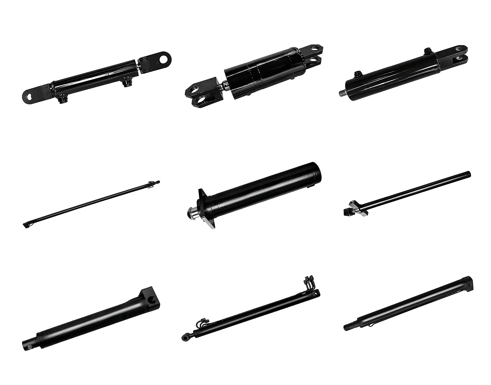
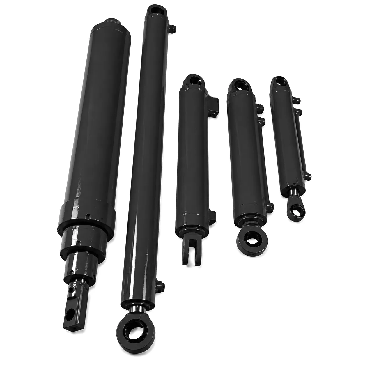
Ever Power complete hydraulic cylinder product range — engineered for demanding UK and global B2B applications
Hydraulic Cylinder Technical & Performance Parameters
The table below captures the key engineering parameters relevant to hydraulic cylinder selection, alignment tolerance, and side load resistance. These figures reflect the standard range available from Ever Power and serve as a reference baseline for engineers specifying cylinders for UK industrial and agricultural applications. Custom configurations beyond these ranges are available upon enquiry.
| Parametr | Standard Range | Notes |
|---|---|---|
| Bore Diameter | 40 mm – 500 mm | Custom bores available on request |
| Długość skoku | 100 mm – 8,000 mm | Long-stroke designs require intermediate support consideration |
| Operating Pressure | Up to 350 bar (standard); up to 500 bar (high-pressure option) | Pressure rating reduces with increasing side load exposure |
| Rod Diameter | 25 mm – 360 mm | Larger rod diameters provide inherently greater side load resistance |
| Max. Permissible Angular Misalignment | 0.05° – 0.1° (fixed mount); up to 3° with spherical bearing | Exceeding limits accelerates seal wear exponentially |
| Cylinder Tube Material | ST52 seamless honed steel; 304/316 SS (corrosive environments) | Induction hardened bore available for enhanced wear resistance |
| Rod Material & Surface Treatment | CK45 / 42CrMo4 steel; hard chrome plated (20–25 µm) | Nickel-chrome duplex plating available for offshore/coastal UK service |
| Seal Material Options | NBR, HNBR, FKM (Viton), PTFE-loaded composite | FKM recommended for high-temperature UK press applications |
| Guide Bush Material | Bronze (CuSn8), PTFE-backed steel, Glacier DU composite | Bronze preferred where side loads are anticipated; longer bush land increases tolerance |
| Operating Temperature Range | -30°C to +120°C (standard NBR/FKM seals) | Low-temperature FKM versions available for Scottish highland/offshore winter service |
| Max. Side Load Capacity (with extended guide) | Up to 15% of rated axial force (engineering approval required) | Consult Ever Power engineering for applications routinely exceeding 5% lateral loading |
| Mounting Options | Flange (front/rear), clevis, trunnion, foot bracket, tie rod | Spherical rod eye bearings standard on articulated-load applications |
Industrial Application Scenarios Where Alignment Is Critical
Across the UK’s most demanding industrial sectors, the cost of misalignment can be measured in downtime, replacement parts, and lost production capacity.
🌾 Agricultural Machinery — Combine Harvesters & Balers
Hydraulic cylinders on combine harvester machines operate in extremely challenging alignment conditions. The header lifts from ground level to transport height across a wide arc, while the uneven terrain of arable fields in Lincolnshire, Yorkshire, and East Anglia introduces unpredictable lateral ground forces through the header attachment frame. Cylinders that do not use spherical rod eye mounts on both attachment points frequently develop accelerated side loading at the header lift position, where the cylinder extends to near full stroke just as the geometric angle of the mounting is at its most acute. Engineers specifying replacement hydraulic cylinders for combine harvesters should prioritise oversized rod diameters and extended guide bush arrangements to absorb the angular variation inherent in these field conditions.
🏭 Heavy Press & Tooling — Birmingham & West Midlands
The precision tooling and press shops of Birmingham and the surrounding Black Country region represent one of the most challenging environments for hydraulic cylinder alignment. Hydraulic press cylinders operating at 200–350 bar on metal forming, punching, and deep drawing operations experience high axial loads combined with the bending moments introduced when tooling is not precisely centred on the cylinder bore. Hydraulic cylinders with flange mounts are standard here, requiring careful shimming of the flange face to ensure that the mounting plate — which often distorts slightly over time due to press bed fatigue — continues to present a truly perpendicular mounting surface to the cylinder axis after years of cyclic loading.
🏗 Construction & Civil Plant — Excavators, Cranes
Mobile plant operating on UK construction sites presents perhaps the widest range of misalignment challenges. Excavator boom and arm cylinders, crawler crane outrigger cylinders, and piling rig crowd cylinders all operate in dynamic geometric environments where the machine constantly repositions itself and the working load changes direction. Cylinder alignment is managed in these applications through the combination of well-maintained clevis pins with precision bronze bushings, and spherical rod eye bearings that provide up to 3° of angular accommodation without transmitting lateral forces to the rod seal pack. Regular bush clearance checks — recommended every 500 operating hours for heavily cycled hydraulic cylinders on UK construction plant — are essential to prevent pin play from creating accumulated misalignment over multiple articulation joints in series.
📣 Lifting Platforms & Scissor Lifts
Custom double acting telescopic hydraulic cylinders for lifting platforms face a particularly complex alignment scenario. As the scissor arms of a mobile elevated work platform extend and retract, the geometry of the cylinder attachment points changes continuously. At low platform heights, the cylinders are close to horizontal and under near-maximum lateral load due to the mechanical advantage of the scissor arms. At full height, the cylinders approach vertical and the side load diminishes significantly. Well-designed lifting platforms manage this through carefully engineered pivot geometry and by sizing the cylinder rod diameter generously relative to the bore — a 1:2 rod-to-bore ratio is common for this application, providing inherent stiffness against the bending moments that arise during mid-height transitions.
Material Selection and Its Role in Side Load Resistance
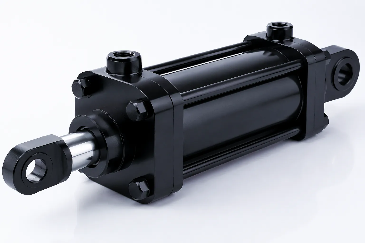
The materials used in a hydraulic cylinder’s construction directly determine how gracefully it absorbs the stresses introduced by side loading. This is not simply a matter of using higher-grade steel throughout — it requires matched selection of tube, rod, guide bush, and seal materials that complement each other’s mechanical and tribological properties under the specific loading conditions of the application.
Cylinder Tube — ST52 Seamless Honed Steel
ST52 (DIN EN 10216) seamless honed steel tube is the industry standard for hydraulic cylinder barrels. Its high tensile strength (520 MPa min.) and consistent bore geometry achieved through precision skiving and roller burnishing create a surface finish of Ra 0.2–0.4 µm, which is essential for seal integrity under lateral contact. The wall thickness is sized using Lamé’s thick-wall cylinder equation accounting for both internal pressure and the secondary bending stress introduced by off-axis loading — a calculation that Ever Power’s engineering team performs as standard during the design phase of all custom-specified hydraulic cylinders.
Piston Rod — 42CrMo4 Alloy Steel + Hard Chrome
For hydraulic cylinders expected to encounter side loads, 42CrMo4 alloy steel — with a minimum tensile strength of 900 MPa and a yield strength exceeding 750 MPa after heat treatment — provides significantly greater bending stiffness than the more common CK45 carbon steel. The hard chrome plating layer (20–25 µm) applied to the rod surface not only provides corrosion protection in the demanding UK coastal and agricultural environment, but its hardness of 850–1,000 HV creates resistance to the micro-scoring that occurs when a side-loaded rod contacts the chrome-on-bronze gland bush interface at an angle. A tighter chrome surface finish (Ra 0.1–0.2 µm) is specified for high-side-load applications to maximise the hydrodynamic oil film over the seal.
Guide Bush — Extended Bronze for Lateral Load Distribution
The guide bush in the gland assembly is the component that carries side loading forces away from the rod seals and into the gland housing. In applications prone to lateral loading, specifying an extended-length bronze guide bush — with a contact length equal to 1.5× the rod diameter rather than the standard 0.8–1.0× — distributes the bending moment over a wider bearing surface, dramatically reducing the contact pressure on the seal land immediately adjacent to the primary rod seal. CuSn8 phosphor bronze is preferred for its combination of compressive strength and the natural lubricating properties of the tin-bronze matrix that sustain a low coefficient of friction even under the increased contact area.
Customer Success Story: Sheffield Steel Press Facility Eliminates Repeat Cylinder Failures
Case Study — Sheffield, South Yorkshire, UK — Metal Forming & Heavy Press Sector
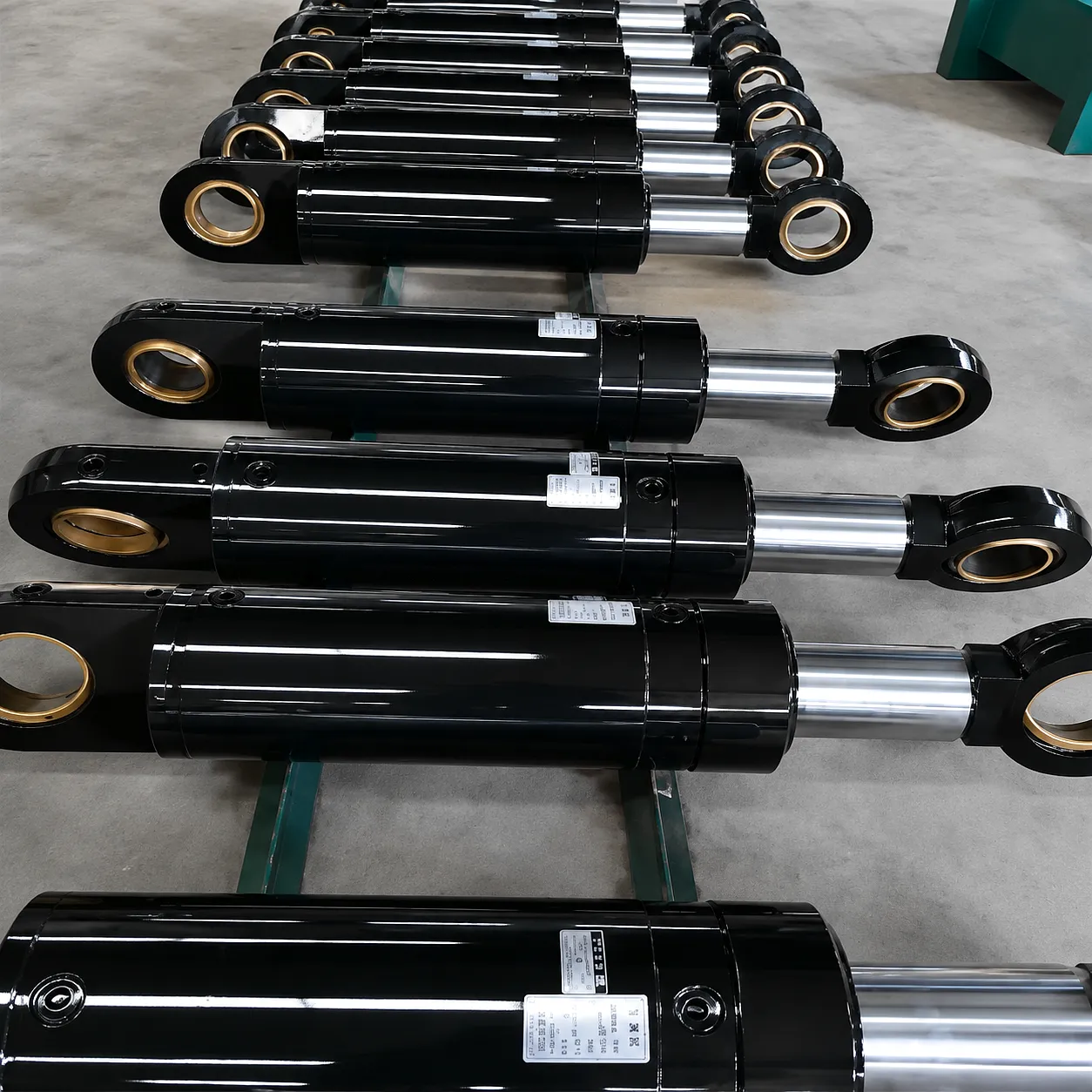
A Sheffield-based steel forming facility operating hydraulic presses for structural section production was experiencing repeated rod seal failures on their primary forming press hydraulic cylinders — averaging a seal replacement every 8–10 weeks on two of their five press lines. The cylinders in question were 160 mm bore, 100 mm rod, rear-flange mounted units operating at 280 bar on a 900-tonne press. Investigation by the plant’s maintenance supervisor, working alongside the Ever Power technical sales team, identified that the press bed — a fabricated steel structure originally designed for a different press tool layout — had been modified twice over the previous decade to accommodate new tooling. Each modification had subtly altered the flatness and perpendicularity of the cylinder mounting face.
Precision dial gauge measurements taken by the facility’s maintenance team confirmed that the rear flange mounting face had a runout of 0.38 mm across its diameter — enough to introduce an angular misalignment of approximately 0.14° in the cylinder axis. While this sounds negligible, at 280 bar with a 100 mm rod, even this small angular offset generated a lateral force at the rod gland of approximately 2.8 kN — sufficient to load one quadrant of the rod seal to 180% of its designed contact pressure, explaining the rapid failure pattern observed.
Ever Power supplied replacement hydraulic cylinders with extended guide bush assemblies (bush land length increased from 80 mm to 130 mm), together with precision-machined steel shim packs to correct the flange face runout. The cylinders were re-fitted with a calibrated torque sequence on the flange bolts and a full load commissioning run was conducted. The result was immediate: zero rod seal failures on either press line in the 14 months following the intervention, and a reduction in hydraulic circuit pressure spikes of over 30% as measured on the system’s pressure transducer logging. The facility’s maintenance supervisor reported that the total cost of the Ever Power intervention — parts, engineering support, and commissioning — was recovered within the first 12 weeks through avoided maintenance downtime alone.
★★★★★
“The extended guide bush option that Ever Power recommended made an immediate, measurable difference to our seal life. We were changing rod seals every two months — it’s now been over a year with zero failures. The technical advice on alignment shimming was spot on and the cylinders were delivered to site within 12 days of the order being placed.”
Maintenance Supervisor — Structural Steel Press Facility, Sheffield
★★★★★
“We specified Ever Power hydraulic cylinders for our new combine harvester header lift system with spherical rod eyes at both ends. After two full harvest seasons in Lincolnshire, the rods show no sign of scoring and the seals are in excellent condition. The 42CrMo4 rod specification gives us confidence in stony field conditions where impact loads are a constant concern.”
Equipment Design Engineer — Agricultural Machinery OEM, Sleaford, Lincolnshire
★★★★★
“We approached Ever Power needing a custom telescopic cylinder for a new scissor lift platform where the geometry created unavoidable side loading through mid-stroke. Their engineering team proposed a rod-to-bore ratio and guide arrangement we hadn’t seen from other suppliers. The custom units arrived dimensionally perfect and have performed without fault on all 18 machines delivered to our UK rental fleet.”
Hydraulic Systems Manager — Access Platform Manufacturer, Coventry
Related Product
Custom Telescopic Hydraulic Cylinders for Lifting Platform — Engineered for Variable Alignment Conditions
Where fixed-length hydraulic cylinders cannot accommodate the geometric variation inherent in scissor-lift and boom-lift mechanisms, Ever Power’s custom telescopic cylinder range provides the extended reach with carefully designed stage-to-stage guide bush arrangements that maintain alignment integrity through all stages of extension. Available in both single and double acting configurations to suit UK aerial work platform and vehicle-mounted lift applications.
Często zadawane pytania
Praktyczne odpowiedzi na najczęściej zadawane przez brytyjskich inżynierów pytania dotyczące ustawienia i obciążenia bocznego.
 Polish
  English
  Italian
  Portuguese
  Dutch
Dutch  Swedish
  Danish
  Finnish
  Hindi
Hindi  Kazakh
  Turkish
  Ukrainian
  Romanian
  Spanish
  German
  Russian
  Korean
  Japanese
  Vietnamese
  Thai
Thai  Indonesian
  Malay
Malay  French
  Greek
Greek