
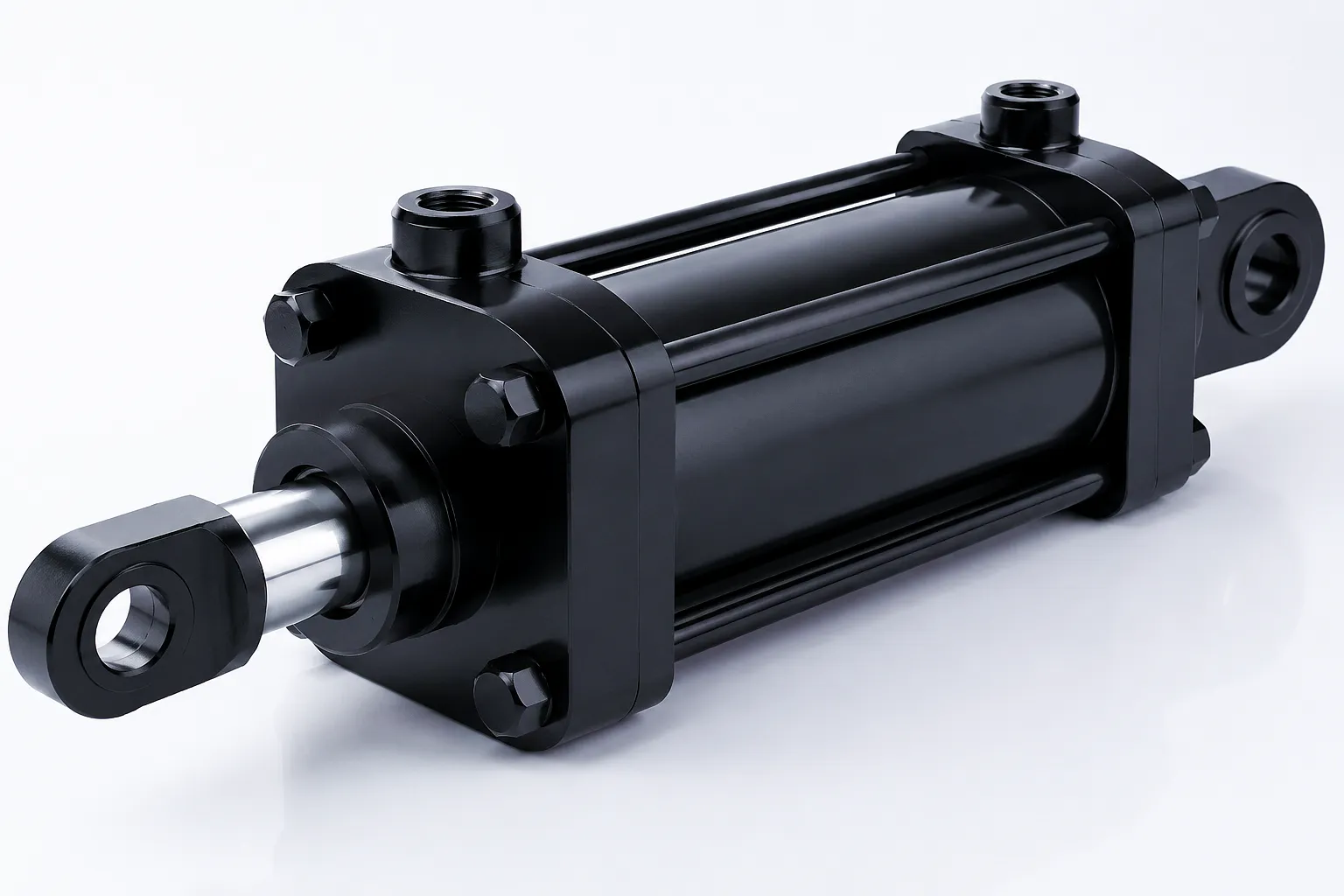
 Choosing the wrong boom cylinder is one of the most expensive mistakes a procurement team can make. Whether you are specifying equipment for a Sheffield steelworks, a Birmingham automotive production line, or a construction fleet working the infrastructure projects expanding across the Midlands, the hydraulic cylinder at the heart of your boom assembly determines the entire lifting envelope, duty cycle reliability, and total cost of ownership of the machine. A bore diameter that is undersized for the working pressure generates heat, accelerates seal wear, and forces the hydraulic pump to work outside its efficient operating range. An overstated stroke length adds unnecessary weight and creates rod column buckling risk under compression. A mounting configuration that is wrong for the structural geometry of the host machine introduces bending moments that the cylinder barrel was never designed to carry. These are not theoretical concerns — they are the failure modes that service engineers across the UK encounter repeatedly, and they are entirely preventable with a structured selection process.
This guide walks through the engineering logic behind each of those three core parameters — bore diameter, stroke length, and mounting style — and explains how they interact with each other and with your application’s real-world operating conditions. It draws on decades of cylinder manufacturing experience and is oriented specifically toward the purchasing and engineering realities of the UK heavy industry and OEM sector, where delivery lead times, compliance with BSEN and ISO standards, and the availability of genuine technical support from the supplier all factor into a sound buying decision.
Working Principle of a Boom Cylinder
Understanding the mechanics before specifying the parameters
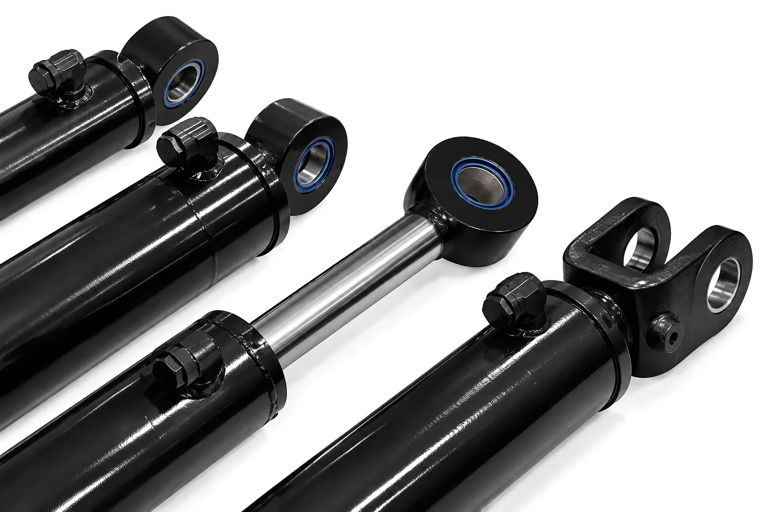
A boom cylinder is a double-acting or single-acting hydraulic linear actuator designed to raise, lower, and hold the boom arm of an excavator, crane, agricultural loader, or other material-handling machine. Pressurised hydraulic fluid — typically mineral oil in the ISO VG 46 or ISO VG 68 viscosity range — enters through a port at one end of the cylinder barrel, acts against the face of the piston, and drives the piston rod outward in extension. When the directional control valve reverses the flow and sends fluid to the rod-side port, the net annular area of the piston (full bore area minus the rod cross-sectional area) generates a retraction force. The ratio of the bore area to the annular area determines the ratio of extension force to retraction force and directly governs the speed differential between the two strokes at a given pump flow rate. This fundamental relationship is the starting point for any credible boom cylinder selection exercise, because the lifting load profile must be matched to the available hydraulic pressure and the pump delivery capacity available in the host machine’s circuit.
Extension Stroke
High-pressure oil enters the cap end port, acts on the full bore face of the piston, and generates maximum pushing force — this is your lifting or crowding power.
Retraction Stroke
Oil enters the rod-side port, acts on the annular piston area. Retraction force is lower than extension force — the rod diameter must be sized to ensure adequate pullback under the machine’s return load.
Hold / Lock
When the directional valve centres, trapped oil in both chambers holds position. Counterbalance valves maintain load against gravity — critical for elevated boom positions in crane and excavator applications.
Bore Diameter: The Foundation of Force Calculation
Getting this wrong invalidates everything downstream
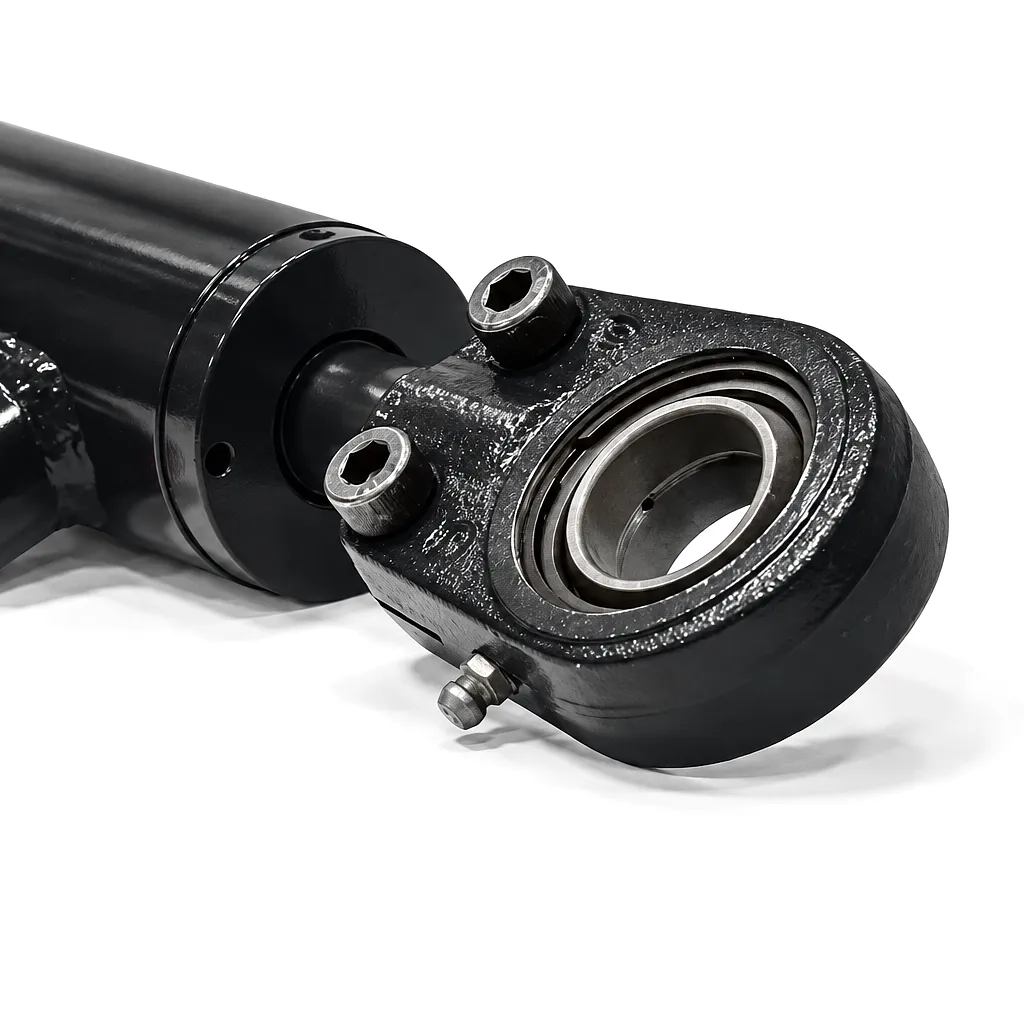 The bore diameter — the internal diameter of the cylinder barrel — is the single most important dimensional decision in the selection process. Extension force equals working pressure multiplied by the bore cross-sectional area. If your hydraulic system operates at 250 bar and you need a theoretical extension force of 196 kN, the minimum bore diameter you can use is 100 mm. In practice, engineers apply a safety factor of 1.25 to 1.5 on top of the theoretical load, which means for a 196 kN application the design force target is between 245 kN and 294 kN, requiring a bore of between 112 mm and 122 mm. Most manufacturers offer bore sizes on preferred ISO series increments — 80, 100, 110, 125, 140, 160, 180, 200 mm — so in this case a 125 mm bore would be the standard selection, providing a comfortable working margin at 250 bar.
There is a secondary effect of bore selection that many procurement teams overlook: flow velocity and heat generation. A larger bore at the same pump flow rate produces a lower oil velocity through the ports and pipework, reduces turbulence, keeps oil temperature lower, and extends seal and fluid life significantly. In UK outdoor plant applications — where winter temperatures can reduce oil viscosity response time and summer ambient temperatures in Birmingham or London can push hydraulic oil towards its upper thermal limit — a bore that gives the system room to breathe thermally is worth its additional cost.
| Bore Ø (mm) | Bore Area (cm²) | Force @ 200 bar (kN) | Force @ 250 bar (kN) | Force @ 315 bar (kN) | Typical UK Application |
|---|---|---|---|---|---|
| 80 | 50.3 | 100.5 | 125.6 | 158.2 | Compact loader arms, access platforms |
| 100 | 78.5 | 157.1 | 196.3 | 247.4 | Agricultural telehandlers, skip lorries |
| 125 | 122.7 | 245.4 | 306.8 | 386.5 | 20–30-tonne excavators, port cranes |
| 160 | 201.1 | 402.1 | 502.7 | 633.4 | Heavy-lift cranes, Sheffield steelworks |
| 200 | 314.2 | 628.3 | 785.4 | 989.6 | Offshore marine, deep-pile drivers |
| 250 | 490.9 | 981.7 | 1,227.2 | 1,546.2 | Tunnel boring machines, large dock cranes |
Stroke Length: Matching Travel to Machine Geometry
Undercalculating or overcalculating the stroke creates structural failure risk
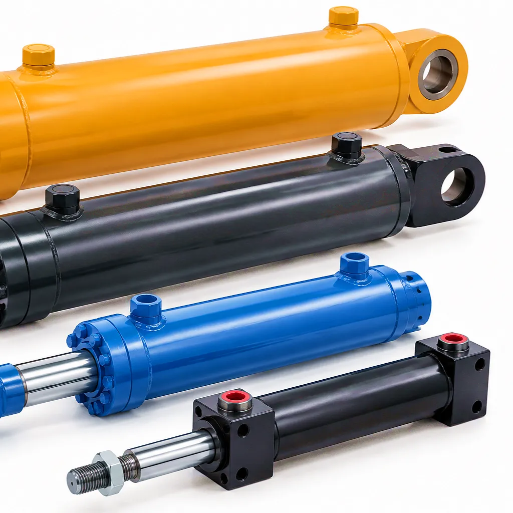 Stroke length defines the linear travel distance of the piston rod from the fully retracted position to the fully extended position. For a boom cylinder, this must correspond precisely to the angular travel the boom arm is required to complete, translated through the geometry of the pin centres. A simple boom with a single pivot point at the base and the cylinder pin located at a fixed point on the boom body can be modelled as a triangle: as the cylinder extends, the angle at the base changes, and the change in the cylinder’s instantaneous length for a given boom angle change is not linear — it follows a trigonometric function. Engineers in Birmingham fabrication shops and Bristol marine yards who dimension cylinders from a single mid-travel angle measurement and then scale linearly typically find their selected stroke is between 8% and 15% short or long. The correct approach is to compute the cylinder length at full retraction (boom at minimum angle) and at full extension (boom at maximum angle) using the cosine rule on the pin-centre triangle, then subtract the two to get the true required stroke.
Once the kinematic stroke is confirmed, the critical structural check is the rod column buckling calculation. A slender cylinder rod extended to a long stroke under compression becomes a Euler column and can buckle sideways under much lower loads than the full bore-pressure force would suggest. The safe buckling load depends on the effective length of the extended cylinder, the rod diameter, the material’s elastic modulus (typically 210 GPa for C45 steel rod), and the end-fixity factor imposed by the mounting arrangement. As a rule of thumb, increasing the stroke length by 20% requires increasing the rod diameter by approximately 10% to maintain the same safety margin against buckling — which in turn slightly increases the annular area penalty on the retraction stroke. These interactions are why the bore, stroke, and rod diameter must be solved simultaneously rather than as independent decisions.
Kinematic Stroke
Determined by machine geometry using the cosine rule on pin-centre triangles. Never estimated from a mid-travel linear approximation.
Buckling Risk
Longer strokes under compression load require larger rod diameters. Safety factor minimum of 3.5 against Euler buckling is standard for boom duty cycles.
Cushioning
End-of-stroke cushioning is strongly recommended on strokes over 800 mm to absorb kinetic energy and protect seals from impact — standard on Ever Power boom cylinders.
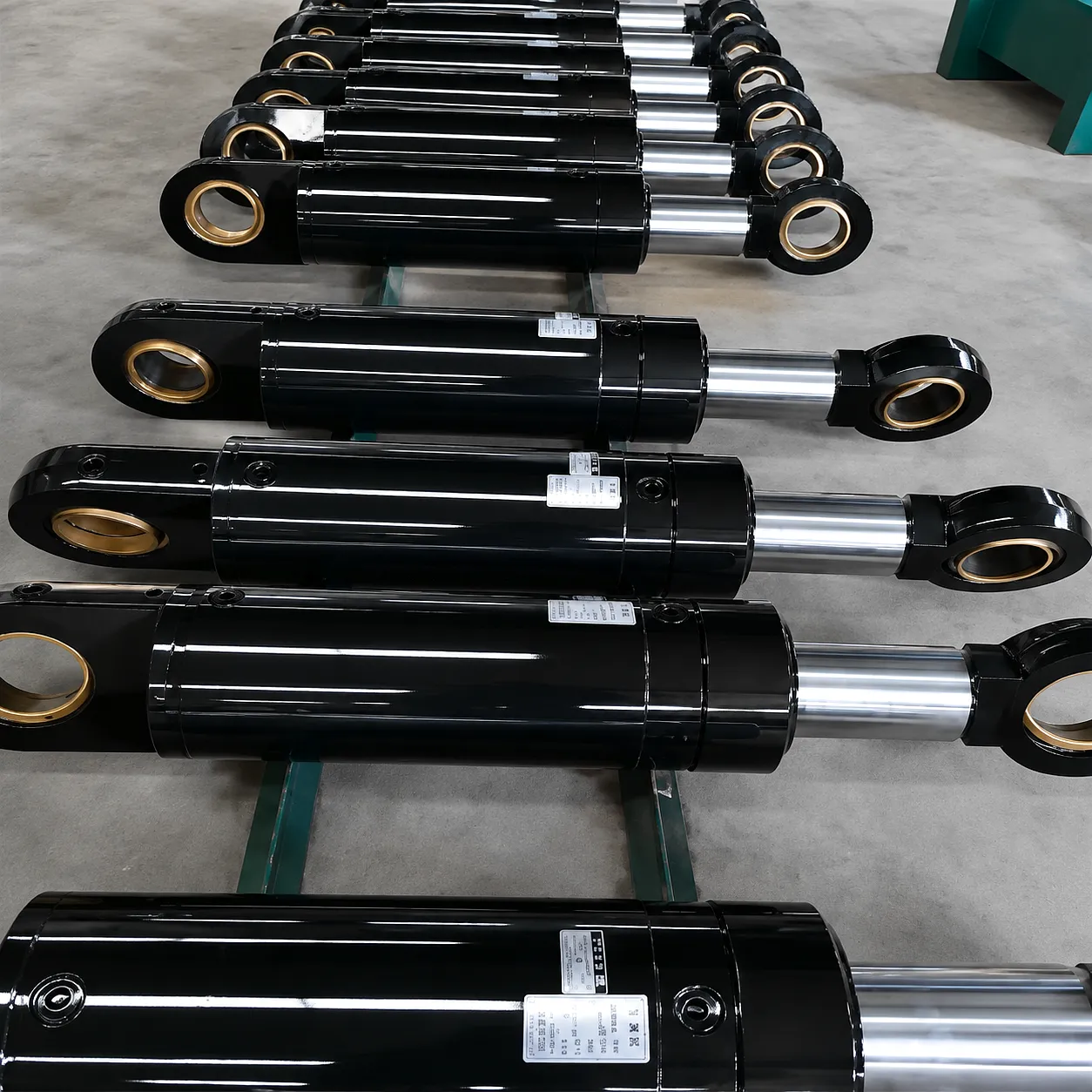
Mounting Configuration: Aligning Force Vector with Frame Structure
The mounting is not just a bolt pattern — it defines how load is introduced into the cylinder body
Clevis / Pin-Eye (Most Common)
The clevis-end and pin-eye configuration is the standard mounting for virtually all mobile boom cylinders. A clevis fork on the cap end and a rod-end eye with through-pin at the piston rod tip allow the cylinder to articulate in a single plane as the boom rotates around its pivot. This arrangement allows the cylinder to naturally follow the changing angle of its own centreline relative to the boom and machine frame. The pin diameter is selected to carry the full bore force divided by the projected pin bearing area at an allowable bearing stress — typically 60–80 MPa for hardened steel pins in bronze-bushed eyes. A common mistake in rebuilt machines across West Midlands plant fleets is fitting metric-dimension pins into imperial-dimensioned eyes, producing a sloppy fit that generates fretting wear and eventually destroys the eye.
Trunnion Mount
Trunnion mounting positions a pair of stub shafts — either mid-stroke or at the cap end of the barrel — that sit in machined bearing housings on the machine frame. This arrangement allows the entire cylinder barrel to pivot, making it ideal for very large cylinders where the mass of the assembly means that a clevis pin at the cap end would introduce excessive bending moments into the end cap. Trunnion-mounted boom cylinders are common in large harbour cranes operating out of Southampton and Liverpool, where the cylinder barrels can exceed 250 mm bore and the installed mass can reach several tonnes. The trunnion bore tolerance and the parallelism of the two trunnion journals must be maintained within close limits — typically within 0.02 mm of coaxiality — to prevent the barrel from trying to skew under side-load conditions.
Flange Mount
Flange mounting bolts the cylinder rigidly to a flat machined face on the machine structure, with the cylinder axis aligned perpendicular to the mounting flange. This mounting is used in applications where the cylinder axis is fixed and the load is collinear with the rod — typically in pressing, clamping, or linear guidance applications rather than rotating boom duty. When a flange-mounted cylinder appears in a boom assembly, it is usually acting as a crowd cylinder pushing a secondary arm rather than as the primary boom lift cylinder. The critical flange design parameter is bolt circle diameter and bolt grade: for a 160 mm bore cylinder at 315 bar, the tensile force on the bolt group in the retraction direction can exceed 400 kN, requiring careful thread engagement and preload torque control to prevent fatigue of the flange fasteners.
| Mounting Type | Articulation | Side-Load Tolerance | Best Application | Relative Cost |
|---|---|---|---|---|
| Clevis / Pin-Eye | Single-plane pivot | Low | Excavators, agricultural loaders, telehandlers | ★★ |
| Trunnion (cap end) | 360° barrel pivot | Very high | Harbour cranes, heavy-lift marine booms | ★★★★ |
| Trunnion (mid-stroke) | 360° barrel pivot | High | Press booms, tipping bodies | ★★★★ |
| Flange (front) | None — fixed | Medium | Crowd cylinders, linear press duties | ★★★ |
| Spherical Eye | Multi-plane | High | Multi-plane booms, offshore equipment | ★★★★★ |
Core Materials and Sealing Technology
Material selection determines longevity in aggressive environments
Barrel — St 52-3 / S355J2
Seamless cold-drawn steel tube with honed inner bore surface. Tolerance H8 on internal diameter; Ra surface finish of 0.4 µm or better to minimise seal friction and wear. Higher-strength CK45 or 42CrMo4 used for extreme-pressure ratings above 350 bar.
Piston Rod — C45E + Hard Chrome
Induction-hardened and precision ground C45E (EN8) steel rod with electrolytic hard-chrome plating to a minimum of 25 µm depth and a Vickers hardness exceeding 800 HV. Corrosion resistance is critical for outdoor UK boom applications — many Ever Power rods are additionally nickel-chrome plated for marine and offshore clients.
Seals — Polyurethane + PTFE
Piston seals are typically Hallite or Parker polyurethane U-cups with a PTFE glide ring for low break-out friction. Rod seals use a primary polyurethane scraper plus a secondary PTFE lip seal with a stainless steel wiper to exclude the field contamination common in UK agricultural and construction environments.
End Caps — Ductile Iron / Steel
Cap ends and gland heads are machined from ductile cast iron or EN24T steel. They carry the port threads — typically BSP or SAE O-ring face seal on UK-specification cylinders — and must be designed to withstand peak pressure spikes that can briefly exceed 1.5× the rated working pressure during machine operation.
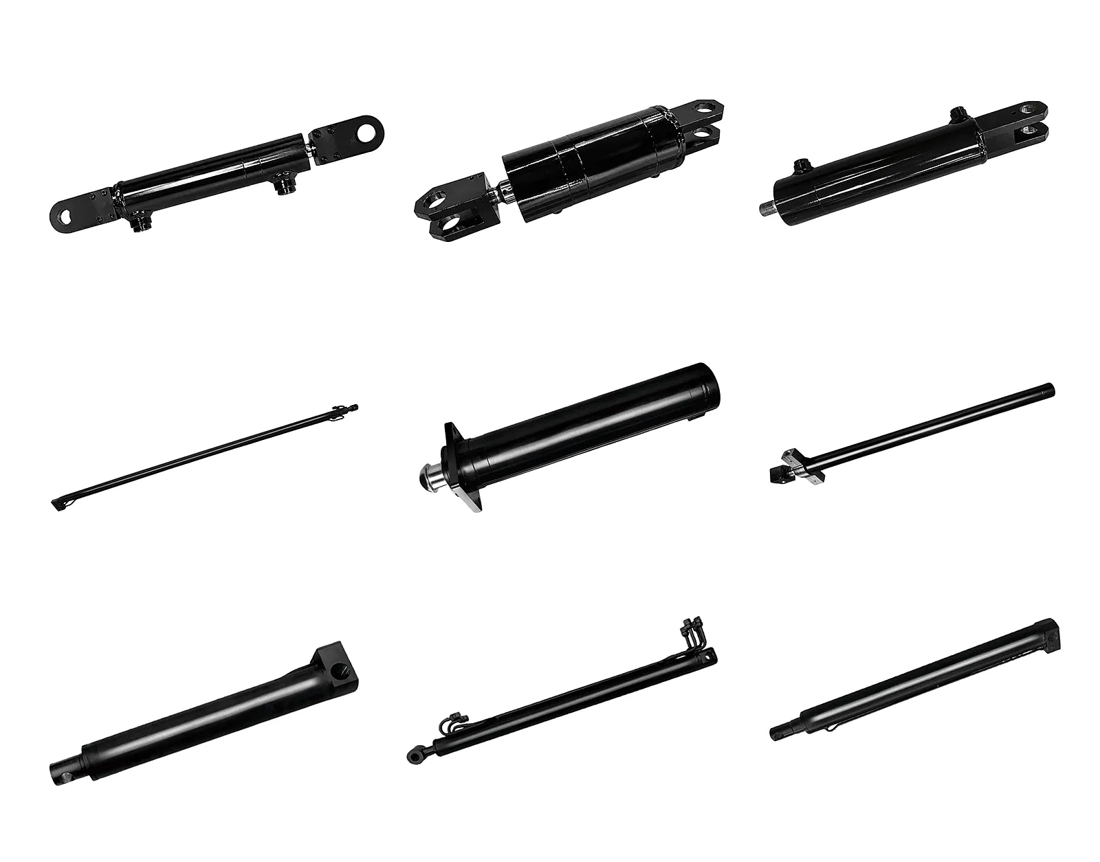
Product Technical and Performance Parameters
Ever Power standard boom cylinder specification range — custom parameters available on request
Industrial Application Scenarios Across the UK
Boom cylinders in the industries that keep Britain’s economy moving
Ever Power: Factory Capability and Customisation Excellence
Precision manufacturing built around your application’s exact requirements
CNC Precision Manufacturing
Ever Power operates a dedicated hydraulic cylinder manufacturing facility equipped with CNC deep-hole boring machines capable of producing honed bores to Ra 0.2 µm, CNC turning centres for rod and end-cap machining, coordinate measuring machines (CMM) for dimensional verification, and hydrostatic pressure test benches rated to 700 bar. The facility’s quality management system is certified to ISO 9001:2015, and all cylinder assemblies destined for UK customers are tested to the customer’s specification before despatch, with a full test certificate provided as standard. For OEM customers requiring traceability, material mill certificates, and weld procedure qualifications, the factory’s documentation management system can provide a complete technical data pack to BS EN 10204 Type 3.1 standard.
Deep Customisation Capability
The strongest part of Ever Power’s offer to UK buyers is not price — it is the ability to manufacture a boom cylinder to a customer’s own drawing in bore sizes and stroke lengths that no catalogue supplier can source. The engineering team accepts customer drawings in STEP, IGES, DWG, or PDF format and returns a dimensioned approval drawing within 48 hours. Customisation options include non-standard bore and rod combinations, special port orientations, integrated position sensors (magnetostrictive or inductive), detachable cushioning inserts, corrosion-inhibiting flush-fill ports for offshore service, and special-purpose end caps with integrated counterbalance valve ports. The minimum order for a fully custom cylinder is one unit, with no tooling fee for bore sizes within the existing hone-tool range.
UK Supply Chain Assurance
Ever Power maintains bonded stock of the most common boom cylinder configurations at a UK-based distribution point, enabling next-day despatch for standard lines. For OEM customers running JIT production lines in the Midlands or the North-East, Ever Power offers a scheduled call-off agreement: a batch is manufactured and held in quarantine stock, released against a release order within a 24-hour turnaround. Import documentation — commercial invoice, packing list, certificate of origin, material test reports — is prepared to UK Border Force requirements as standard, avoiding the delays that have affected less organised suppliers since the post-Brexit customs regime came into force.
Customer Success Story: Grimsby Port Materials Handling
How a Humber estuary port authority solved a persistent cylinder failure problem
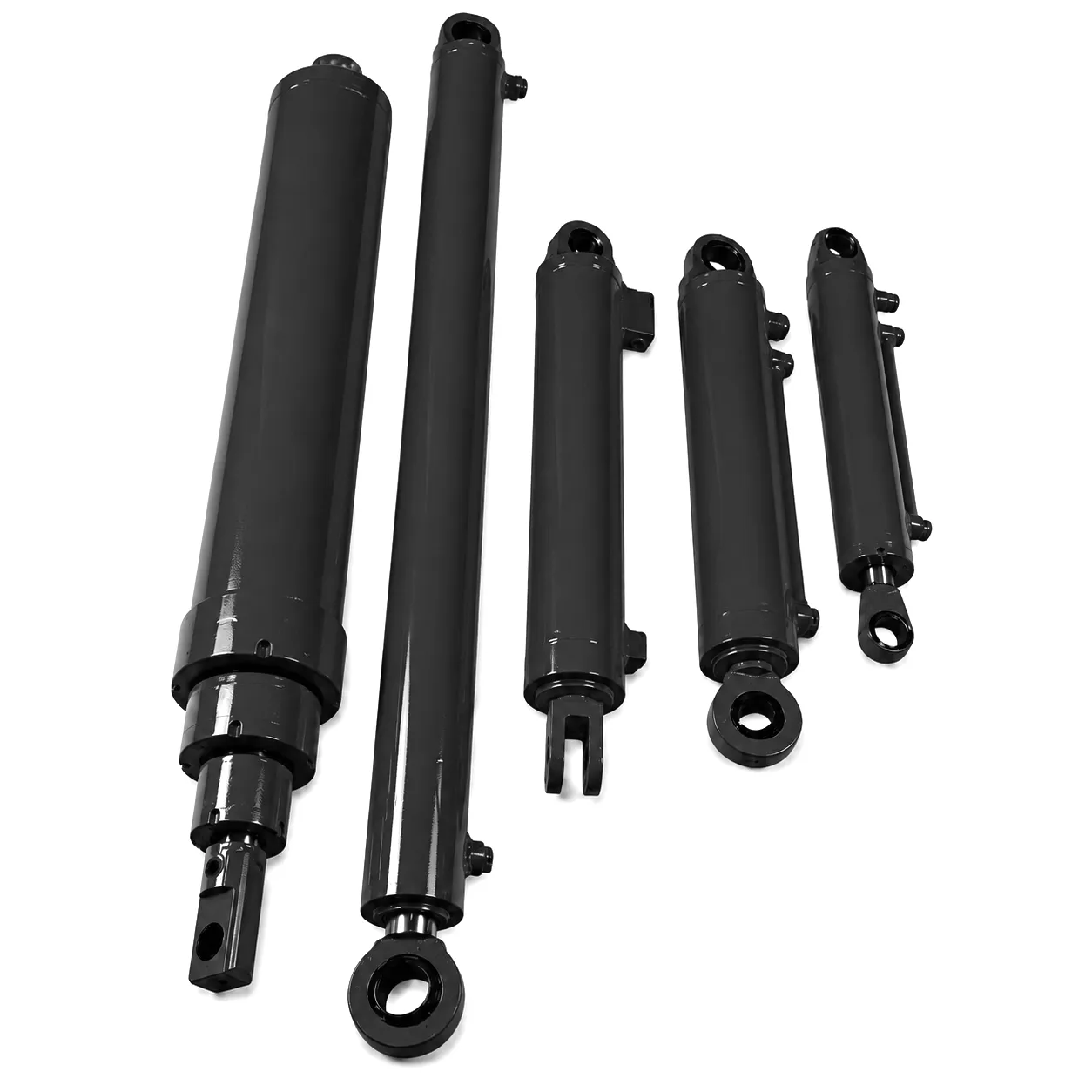
A port authority operating bulk cargo handling cranes at the Port of Grimsby on the Humber estuary had experienced recurring boom cylinder failures on their shore-side rail-mounted grab cranes. The cylinders in question — 160 mm bore, 2,200 mm stroke, clevis-mounted — were sourced from a European distributor and had been delivering a service life of approximately 900 operating hours before rod seal failure became evident through visible weeping at the gland. With the cranes operating around the clock during the grain harvest season and during coal discharge operations, a 900-hour seal life translated to a forced outage every six to eight weeks for an unscheduled seal replacement that required crane shutdown and a specialist hydraulics contractor on site.
The port’s mechanical engineering team contacted Ever Power to undertake a failure analysis of the returned cylinders. The root cause was identified as a combination of factors: the existing rod was finished to a surface roughness of Ra 0.6 µm rather than the specified Ra 0.2 µm, the hard-chrome plating depth was measured at 14–17 µm rather than the minimum 25 µm stated on the drawing, and the rod wiper was a standard polyurethane lip seal with no metallic backup, allowing fine salt-laden sand to breach the seal during tidal conditions when the crane was not operating.
Ever Power manufactured a direct-replacement set of eight boom cylinders to a revised specification: Ra 0.2 µm rod finish, 30 µm hard-chrome plating verified by magnetic pull-off test, a duplex rod seal system with a primary PTFE-backed Viton wiper and a stainless steel scraper ring, and an ISO 12944 C5-M paint system on all external steel surfaces. The cylinders were delivered to Grimsby in 16 working days from order confirmation, all arriving with full 3.1 material certificates and pressure test records. Following installation, the cylinders completed 3,800 operating hours without a seal change — a service life improvement of over four times — before the port’s next scheduled maintenance shutdown.
“The engineering support from Ever Power before order was as good as anything we get from domestic UK suppliers. They reviewed our existing cylinder drawing, flagged the rod finish issue without being asked, and came back with a revised spec that we would never have specified ourselves. The cylinders have been running for ten months now without a single leak. That is genuinely transformative for our crane availability figures.”
James Hargreaves
Chief Mechanical Engineer — Grimsby Port Authority
“We specified a non-standard bore and stroke combination that our previous supplier told us would require minimum order quantities of twenty-five units. Ever Power produced one prototype unit in two weeks and held the rest on a six-month call-off agreement. The customisation flexibility is genuinely remarkable for a supplier at this price point, and the 3.1 certificates arrived with the goods — no chasing required.”
Rachel Thornton
Procurement Manager — Sheffield Precision Engineering Ltd
“Our offshore wind vessel had two boom cylinders fail within a week of each other during an installation campaign off the East Anglian coast. Ever Power airfreighted replacement units from their factory to our operations base at Great Yarmouth in under five days. The cylinders were accompanied by full test documentation and slotted straight into the existing mountings without modification. The response to an urgent situation was impressive.”
David Carmichael
Hydraulics Superintendent — North Sea Marine Contractors Ltd
Często zadawane pytania
Answers to the questions UK engineers and buyers ask most often
Ever Power — Precision Hydraulic Cylinders for UK Industry
Ready to Specify Your Boom Cylinder?
Send your drawing, dimensions, or application details and receive a full technical quotation within 24 hours — with BSP ports, 3.1 certs, and DDP UK delivery as standard.
© 2026 Ever Power Group — Hydraulic Cylinder Engineering & Manufacturing | edit by gzl
 Polish
  English
  Italian
  Portuguese
  Dutch
Dutch  Swedish
  Danish
  Finnish
  Hindi
Hindi  Kazakh
  Turkish
  Ukrainian
  Romanian
  Spanish
  German
  Russian
  Korean
  Japanese
  Vietnamese
  Thai
Thai  Indonesian
  Malay
Malay  French
  Greek
Greek