
Why Seal Selection Decides Whether Your Hydraulic System Succeeds or Fails
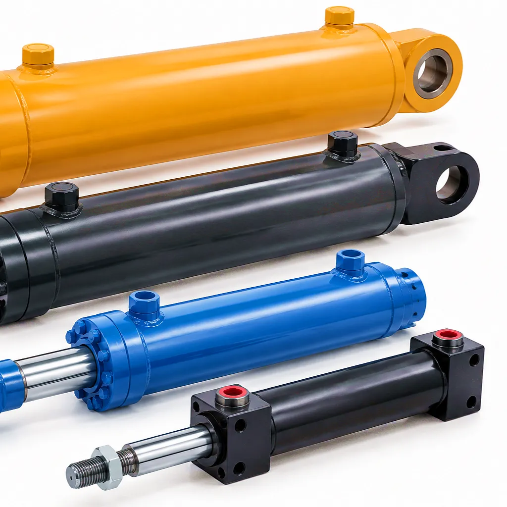 In the engineering of hydraulic cylinders, the difference between a system that operates reliably for thirty thousand cycles and one that fails within the first season often comes down to a component most engineers underestimate: the seal. Whether specified for a forklift mast in a Birmingham distribution warehouse, a telescopic boom on a construction site in Sheffield, or a precision welding arm in a Midlands automotive plant, the seal package determines how the entire hydraulic cylinder behaves under pressure, temperature variation, and continuous mechanical stress.
Need a custom hydraulic cylinder with engineered seal specifications? Our technical team responds within 24 hours.
Understanding the Core Distinction: Motion vs Containment
Dynamic Seals
Dynamic seals function across a sliding or rotating interface. In a hydraulic cylinder, this means the seal must maintain contact pressure against a moving surface — typically the reciprocating piston rod — while allowing controlled, low-friction motion through tens of thousands of cycles. The engineering challenge here is contradictory by nature: the seal must be tight enough to prevent hydraulic fluid bypass yet compliant enough not to generate destructive friction heat. Rod seals, piston seals, and wiper seals all fall within this category. Each must contend with the hydrodynamic film that forms between the seal lip and the rod surface, which both lubricates the interface and contributes to the micro-leakage that accumulates over time. The geometry of the sealing contact zone, expressed as the contact pressure distribution curve, determines both the friction coefficient and the fluid film thickness — two variables that pull in opposite engineering directions.
Static Seals
Static seals operate between two surfaces that do not move relative to each other once the cylinder is assembled. Their sole obligation is containment — preventing hydraulic fluid from migrating across a fixed joint face. End-cap O-rings, back-up rings behind threaded glands, and face seals on port fittings are all static in operation. Because there is no relative motion, the design priorities shift from friction management and wear endurance to compression set resistance, chemical compatibility, and long-term elastic recovery. A static seal that has lost its elastic memory — through thermal cycling, chemical attack, or simple age hardening — will no longer exert the contact pressure necessary to maintain a zero-leak interface. The failure mode is gradual and often insidious: a weeping joint that worsens incrementally until a maintenance intervention becomes unavoidable. Understanding this degradation pathway is essential for any plant engineer responsible for hydraulic assets across facilities in Sheffield, Coventry, or Glasgow.
Seal Material Science: What Goes Into a Reliable Hydraulic Cylinder Seal
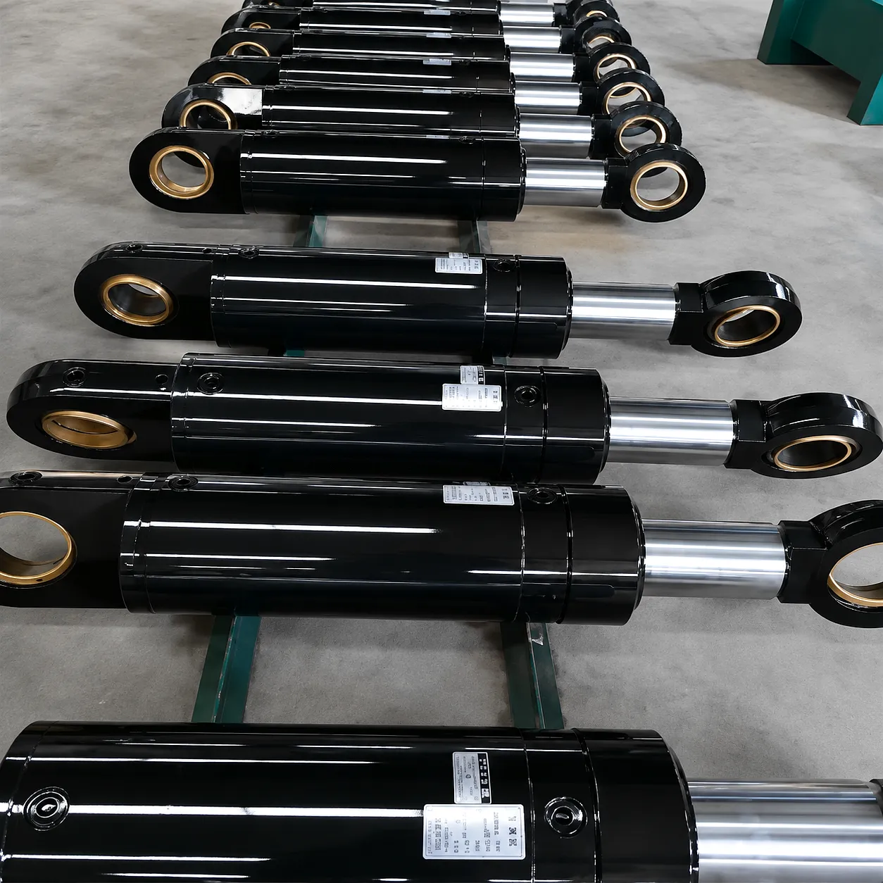
The material composition of a hydraulic cylinder seal is not a default choice — it is an engineering specification driven by operating pressure, fluid type, temperature range, and the chemical environment the cylinder will encounter throughout its service life. For UK industrial users operating across manufacturing, construction, and agriculture, these variables shift dramatically depending on the application. A seal running in a cold-press hydraulic system in a Leeds food processing plant faces an entirely different chemical exposure profile than one embedded in a high-pressure telescopic cylinder used on a boom lift operating offshore in Aberdeen. Seal material selection is the single most consequential decision in the sealing system design.
Nitrile Rubber (NBR)
Nitrile rubber — also written as Buna-N — remains the most widely used elastomer in hydraulic cylinder sealing, and for straightforward reasons: it offers an excellent balance of oil resistance, mechanical strength, and cost-effectiveness across a temperature window running from approximately -40°C to +120°C. NBR performs reliably with mineral-based hydraulic fluids, the most common fluid type in UK industrial hydraulics. It shows strong resistance to abrasion and compression set when formulated correctly. The primary limitations emerge in environments involving ozone exposure, ketone-based fluids, or temperatures that consistently exceed its upper threshold — conditions that trigger surface cracking and premature hardening. For general manufacturing hydraulics across the Midlands and the North of England, NBR remains the sensible default for both rod seals and piston seals where fluid compatibility is confirmed.
Polyurethane (PU)
Polyurethane seals occupy a distinct performance tier above standard NBR in applications demanding high mechanical strength and excellent resistance to extrusion under elevated system pressures. PU seals can sustain operating pressures of 350 bar or more without the progressive extrusion failure that would destroy a softer elastomer in the same groove. They exhibit outstanding abrasion resistance — typically three to five times better than NBR — making them the preferred choice for hydraulic cylinder rod seals in mobile machinery operating in abrasive environments such as quarrying, tunnelling, or demolition. Common in boom cylinders on telehandlers and aerial platforms across UK construction sites, PU seals run effectively across a temperature range of -30°C to +100°C. The material is sensitive to hydrolysis in high-humidity environments over extended periods, which must be factored in for cylinders stored or operating outdoors in the UK’s wet climate.
FKM / Viton
Fluorocarbon elastomers — marketed under brand names including Viton — define the top tier of seal material performance for thermally and chemically demanding hydraulic applications. FKM retains full sealing function at continuous operating temperatures up to +200°C, and exhibits exceptional resistance to aromatic hydrocarbons, phosphate ester fluids, ketones, and a wide spectrum of industrial chemicals that would rapidly destroy NBR or PU seals. For hydraulic cylinders working in steel mills, chemical processing, and offshore platforms — environments found across Scotland, Teesside, and South Wales — FKM sealing systems represent the correct specification even though the unit cost is significantly higher than alternative materials. FKM compression set resistance is superior across the temperature range, meaning the seal retains its installed force over years of service. In static sealing applications such as end-cap O-rings in high-temperature presses, FKM is frequently the only material that meets the service life requirement.
PTFE (Polytetrafluoroethylene)
PTFE is not an elastomer — it does not self-energise through its own elastic recovery — which means it almost always appears in hydraulic cylinder sealing as a composite or spring-energised element rather than a standalone seal. Its value lies in an extraordinarily low friction coefficient, near-universal chemical inertness, and a service temperature range stretching from -200°C to +260°C. In dynamic sealing applications where stick-slip must be eliminated — precision machine tool cylinders, medical equipment actuators, and servo-controlled hydraulics in automated manufacturing — spring-energised PTFE rod seals deliver consistent, predictable breakaway and running friction. PTFE back-up rings routinely pair with NBR and FKM O-rings to prevent extrusion at high system pressures. In water-based hydraulic fluid systems, where many traditional elastomers face compatibility challenges, PTFE-based sealing components offer a reliable solution.
Groove Design: The Geometry That Makes or Breaks Seal Performance
A hydraulic cylinder seal is only as effective as the groove that houses it. The groove provides the structural environment in which the seal is compressed, positioned, and held against the mating surface throughout the full pressure and temperature cycle of operation. Groove design errors — whether in width, depth, corner radius, or surface finish — produce failure modes that are often misattributed to seal material quality when the root cause is dimensional. Understanding what correct groove geometry looks like, and why the tolerances are tight, is fundamental to specifying or troubleshooting hydraulic cylinder sealing systems.
Compression Ratio Control
For static O-ring grooves, the standard compression ratio lies between 15% and 25% of the O-ring’s cross-sectional diameter. Too little compression — below 10% — and the seal contact pressure is insufficient to maintain a positive seal against system pressure; too much — above 30% — and the seal experiences permanent compression set during installation, eliminating its long-term elastic recovery. The groove depth must therefore be machined to tolerances of ±0.025 mm or tighter, a requirement that demands precision CNC turning capability. At Ever Power, groove machining is performed on computer-controlled lathes with in-process measurement, ensuring that the specified compression ratio is achieved consistently across batch production. For dynamic seals, the allowable compression range narrows further because excess interference translates directly into elevated friction and accelerated wear at the seal lip contact zone.
Surface Finish Requirements
The surface roughness of both the groove bore and the rod or bore surface that contacts the dynamic seal is specified in Ra (arithmetic mean roughness) values. For hydraulic cylinder rod surfaces in contact with polyurethane or NBR rod seals, the industry standard finish ranges from Ra 0.1 µm to Ra 0.4 µm — achieved through hard chrome plating followed by centreless grinding and polishing. Too smooth a surface (below Ra 0.05 µm) can impair the formation of the lubricating oil film, paradoxically increasing friction and accelerating wear. Too rough a surface (above Ra 0.6 µm) causes abrasive damage at the seal lip contact zone, generating fine particles that contaminate the fluid and score the rod surface further. This precise surface finish requirement explains why hydraulic cylinder rod chrome plating is a precision engineering process, not simply a corrosion protection measure.
Back-Up Ring Integration
Where operating pressures exceed 100 bar, a standard O-ring in either a static or dynamic groove will extrude progressively into the diametral clearance gap between the housing and the mating component. This extrusion eventually severs the seal, producing sudden catastrophic leakage. The engineering solution is the back-up ring — a rigid or semi-rigid PTFE or acetal ring installed on the downstream pressure side of the O-ring, physically blocking the extrusion pathway. For high-pressure hydraulic cylinders — those operating at 250 bar and above, common in UK heavy industry — double-sided back-up ring arrangements are required on both flanks of the O-ring. The groove width must accommodate both the seal and the back-up ring within the tolerance envelope, a design constraint that tightens the dimensional requirements on the entire groove machining sequence.
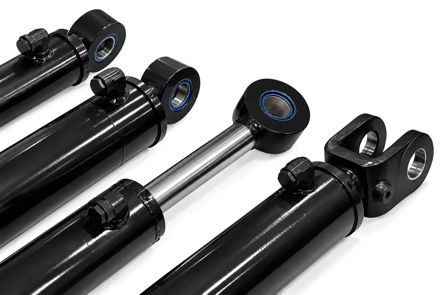
Seal Material Technical Performance Parameters
| Property | NBR | Polyurethane | FKM / Viton | PTFE |
|---|---|---|---|---|
| Faixa de temperatura | -40°C to +120°C | -30°C to +100°C | -20°C to +200°C | -200°C to +260°C |
| Max Operating Pressure | 200 bar | 400 bar | 350 bar | 700 bar (energised) |
| Friction Coefficient | 0.06 – 0.10 | 0.04 – 0.08 | 0.05 – 0.09 | 0.01 – 0.03 |
| Mineral Oil Resistance | Excellent | Excellent | Excellent | Excellent |
| Abrasion Resistance | Good | Excellent | Good | Moderate |
| Hardness (Shore A) | 70 – 90 | 80 – 95 | 70 – 90 | 55 – 65 (Shore D) |
| Compression Set (70 hrs / 100°C) | 15 – 25% | 20 – 35% | 10 – 18% | N/A (non-elastic) |
| Primary Applications | General hydraulics, rod / piston seals | Mobile machinery, boom cylinders | High-temp / chemical environments | Precision servo, ultra-low friction |
| Custo Relativo do Material | Low | Medium | High | Medium–High |
Folding Boom Angle Cylinder
1458mm stroke aerial work vehicle cylinder — polyurethane rod seal package optimised for repeated extension cycles in UK construction environments. Groove dimensions machined to ISO 6547 tolerance class.
Cilindro de ângulo da lança principal
555mm stroke main boom cylinder with a composite sealing system — static FKM O-rings at the end caps combined with polyurethane dynamic rod seals — delivering leak-free operation in aerial platform applications.
Hydraulic Cylinder Seal Failure Modes: Diagnosis and Root Cause
Hydraulic cylinder seal failure is rarely a random event. Each failure mode carries distinctive physical evidence — from the discolouration of a heat-degraded FKM O-ring to the spiral cut pattern on a nitrile rod seal that encountered an improperly chamfered groove edge. Developing the diagnostic capability to read that evidence accurately, and trace it back to a specific root cause, is the difference between fixing a cylinder and fixing the problem that destroyed it. The following failure pathways cover the most common mechanisms encountered across UK industrial hydraulic systems.
⚠ Extrusion Failure
Extrusion occurs when hydraulic pressure forces the seal material into the clearance gap between the rod and the housing. The extruded material shears off as the cylinder cycles, generating hard debris particles that circulate through the fluid circuit and accelerate wear on valve spools, pump internals, and cylinder bore surfaces. Extrusion appears primarily in high-pressure applications where the diametral clearance gap exceeds the seal material’s resistance to cold flow at the prevailing pressure and temperature. The solution is invariably a combination of reduced clearance, harder seal compound selection, or the addition of anti-extrusion back-up rings. Cylinders operating in heavy pressing applications across Sheffield’s metal forming sector frequently encounter this failure mechanism when original seal specifications are not upgraded to match process intensification over time.
⚠ Compression Set Failure
A seal suffering from compression set has lost the elastic recovery that allows it to maintain contact pressure against the sealing surface as the groove geometry fluctuates under thermal cycling and pressure variation. The physical evidence is an O-ring or lip seal that, when removed from the groove, retains a permanently flattened profile rather than returning to its circular cross-section. Once compression set exceeds approximately 40% of the original cross-sectional diameter, the seal can no longer generate adequate contact stress at low or zero pressure, and the joint begins to weep. This failure mode is strongly associated with extended service at elevated temperatures, chemical attack that accelerates elastomer aging, and incorrect material specification. Static seals in end-cap glands of hydraulic cylinders installed in UK foundry and heat-treatment plant are particularly susceptible if NBR is specified in environments where FKM or silicone would be the appropriate choice.
⚠ Spiral Failure
Spiral failure is a dynamic-seal-specific failure mode that affects O-rings operating in sliding applications — particularly piston seals in long-stroke cylinders. The failure mechanism begins when uneven friction across the contact width causes the O-ring to roll rather than slide during the piston stroke. After several cycles of rolling, the torsional stress induces a helical cut that propagates through the O-ring cross-section, splitting it along a spiral path. The cut is distinctive and serves as a reliable diagnostic indicator — a helically split O-ring confirms spiral failure as the mechanism. Prevention requires optimising groove dimensions to the specific O-ring size, ensuring the correct surface finish on the bore, and maintaining adequate fluid lubrication. For long-stroke telescopic hydraulic cylinders — common on agricultural equipment operating across Yorkshire and East Anglia — spiral failure is one of the most frequently encountered dynamic seal degradation mechanisms.
⚠ Abrasive Wear at the Wiper Seal
The wiper seal is the outermost dynamic seal element in a hydraulic cylinder, and its sole function is to prevent ingress of external contamination — dust, grit, water, and metallic particles — onto the rod surface before it re-enters the cylinder. When the wiper seal degrades, whether through UV embrittlement, mechanical damage, or simply exhausted service life, contamination enters the cylinder unchecked and rapidly overwhelms the rod seal’s capacity to maintain a clean sealing interface. The abrasive particles carried into the cylinder on the returning rod act as a grinding compound at the rod seal contact zone, producing accelerated lip wear and ultimately catastrophic rod seal failure. For hydraulic cylinders operating on mobile machinery in outdoor UK conditions — particularly during the winter months when road salt, grit, and persistent rain contaminate exposed cylinder rods — wiper seal inspection and replacement intervals must be treated with the same priority as the primary sealing elements.
Industrial Application Scenarios for Hydraulic Cylinder Sealing Systems
🏗 Construction and Civil Engineering — Birmingham, Coventry
Hydraulic cylinders in excavators, piling rigs, and concrete placing booms operate in some of the most contamination-rich environments in any UK industry. The sealing requirement combines polyurethane dynamic rod seals for their abrasion resistance with heavy-duty multi-lip wiper seals that exclude the site contamination characteristic of Midlands construction and infrastructure projects. Telescopic boom cylinders used on mobile elevated work platforms demand composite sealing systems where the rod seal maintains fluid containment across the full stroke range while the wiper strip protects the chrome rod surface from Birmingham’s clay-laden soils and construction dust.
🔨 Steel and Metals Processing — Sheffield, Rotherham
Sheffield’s steel sector places some of the most demanding thermal and chemical stress on hydraulic cylinder sealing systems of any UK industry. Tilt cylinders on continuous casting machines, and positioning actuators on rolling mill stands, operate at ambient temperatures that can exceed 80°C continuously, with radiant heat spikes significantly above that figure. FKM seals are the correct specification for these applications, both in the dynamic rod seal positions and as static seals at all end-cap interfaces. Back-up ring arrangements on both flanks of every static O-ring are standard practice given the pressure levels involved. The steel industry’s hydraulic fluids are often fire-resistant phosphate ester types — compounds that are incompatible with NBR and will cause rapid seal degradation if the wrong material is installed.
🌿 Agricultural Machinery — Yorkshire, East Anglia
Agricultural hydraulic cylinders — operating on tillage equipment, baler rams, combine harvester header lifts, and plough reset systems — face seasonal contamination from soil, crop residue, and fertiliser chemicals that attack exposed rod surfaces and wiper seals aggressively. The UK’s agricultural heartlands across Yorkshire, Lincolnshire, and East Anglia put cylinders into service under wet, cold conditions at the start of the season, transitioning to dusty, hot harvesting periods by August. A sealing system that functions reliably across this temperature and contamination range requires multi-material selection: NBR piston seals for general compatibility, PU rod seals for durability, and robust polyurethane or TPU wiper seals with a dirt-exclusion geometry specifically designed for agricultural use.
🏭 Automotive Manufacturing — West Midlands
Press shop hydraulic cylinders in West Midlands automotive plants operate at high cycle frequencies and elevated pressures, demanding seal packages that maintain precise dimensional stability over millions of cycles without exhibiting the stick-slip behaviour that would introduce positional error in press tooling. Spring-energised PTFE rod seals are frequently specified here, delivering the consistent breakaway and running friction characteristics that servo-controlled press systems require. Static seals throughout these cylinders are specified in FKM to handle the synthetic and semi-synthetic hydraulic fluids common in clean-room adjacent manufacturing environments. The quality standards applied by Jaguar Land Rover, BMW, and other West Midlands automotive manufacturers cascade directly into the sealing specifications demanded of hydraulic cylinder suppliers.
Ever Power Manufacturing: Precision Sealing Systems, Built to Your Specification
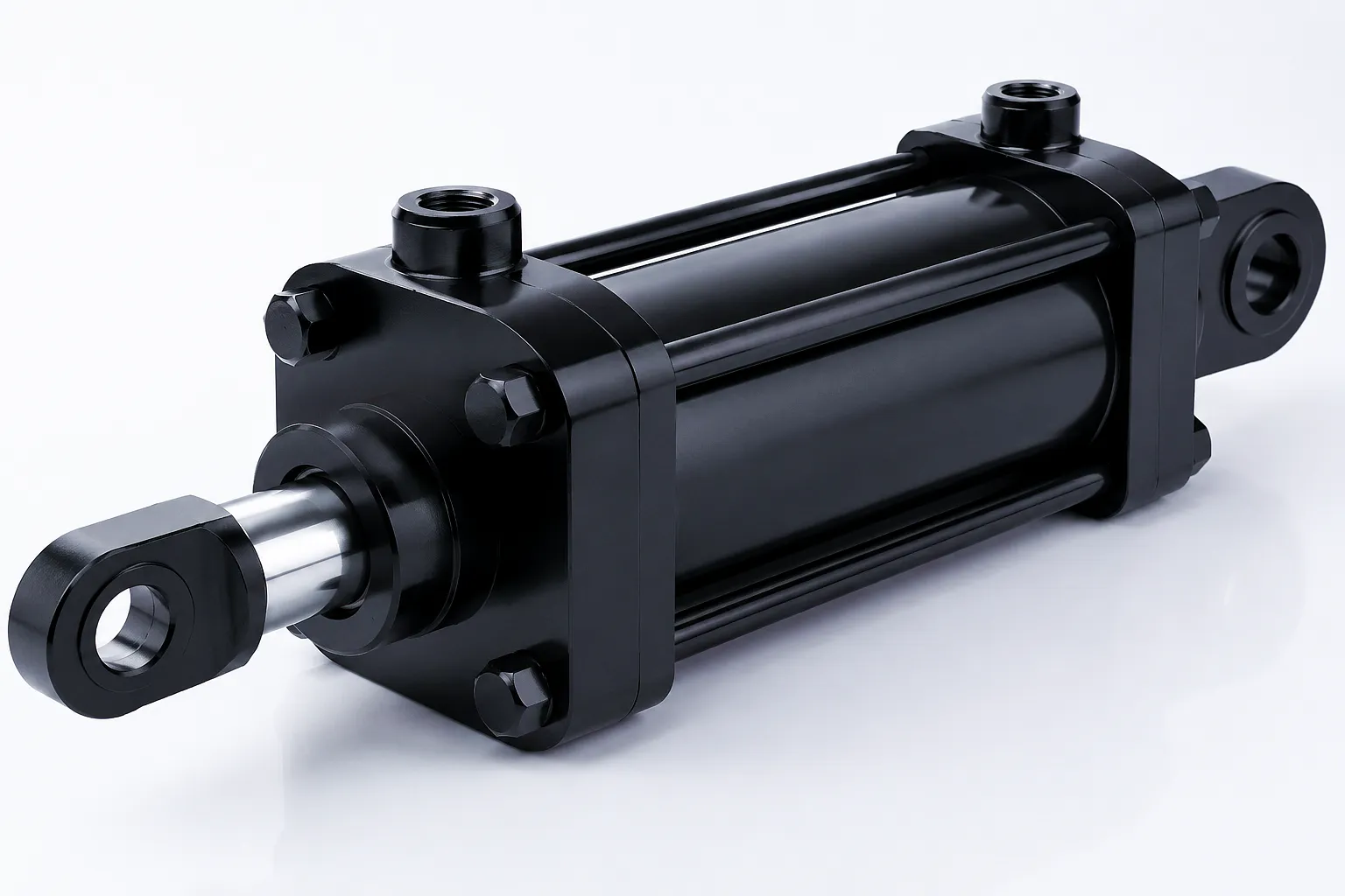
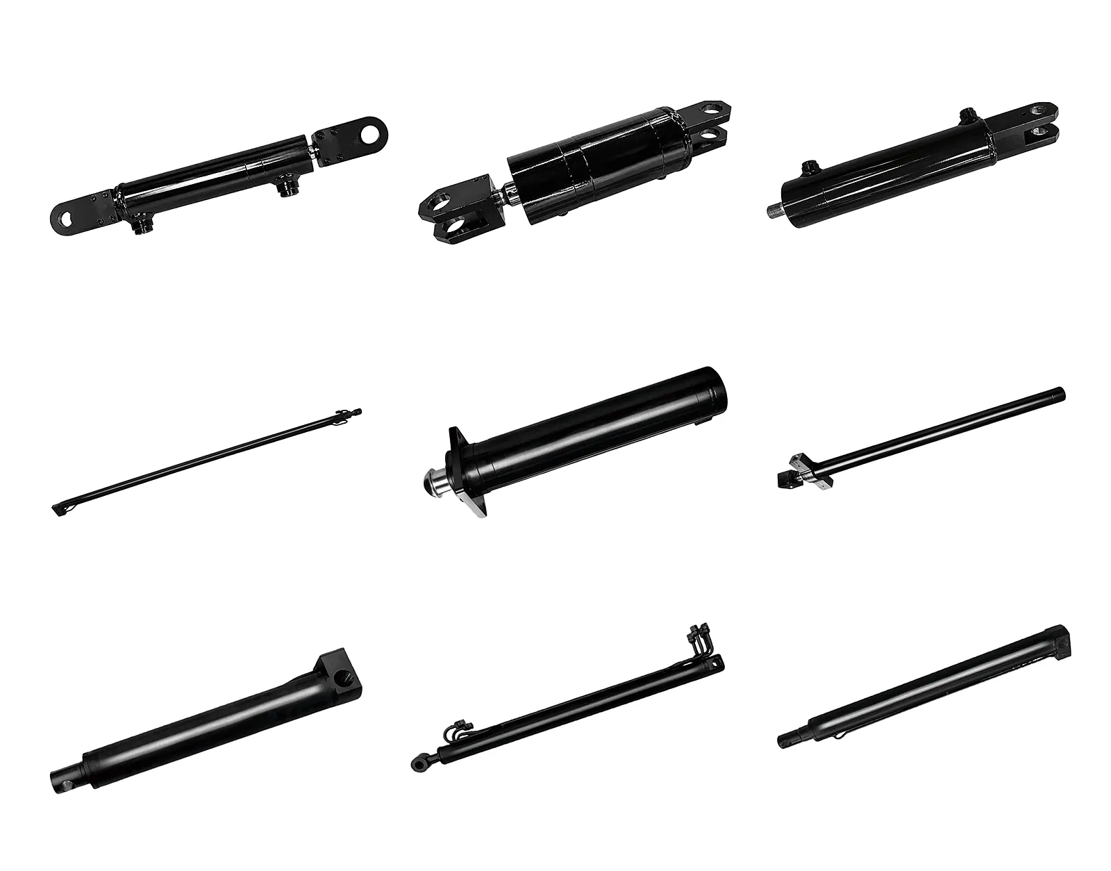
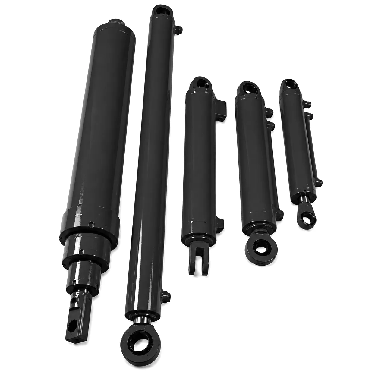
Ever Power operates hydraulic cylinder manufacturing facilities with a direct focus on engineered sealing solutions for industrial applications across the UK and global markets. The company does not offer catalogue seals for generic applications — every sealing system supplied by Ever Power is developed in response to a specific set of operating conditions, fluid compatibility requirements, and service life targets defined by the customer’s technical team. This approach to customisation begins with the seal material selection and extends through groove geometry specification, surface finish requirements, and the dimensional tolerancing of every component in the sealing system.
CNC Groove Machining
Groove dimensions are machined on four-axis CNC lathes with in-process gauging. Tolerances of ±0.015 mm on groove depth are held as standard — well within the requirement for Class 1 sealing groove accuracy per ISO 6547. Every groove is inspected against a digital dimension protocol before the seal assembly stage, ensuring that compression ratios are achieved as specified across the full production run.
Rod Surface Preparation
Hard chrome plating is applied to hydraulic cylinder rods to a standard thickness of 25 µm to 50 µm, followed by centreless grinding and polishing to achieve a rod surface finish of Ra 0.1 µm to Ra 0.4 µm. For applications demanding enhanced corrosion resistance — relevant for UK offshore and coastal industrial installations — nickel chrome duplex plating is available, maintaining the same surface finish parameters while providing superior protection against salt spray and humidity.
Pressure Test and Validation
Every hydraulic cylinder manufactured by Ever Power undergoes a full-stroke pressure test at 1.5 times the specified working pressure before despatch. The test protocol includes dynamic cycling — a minimum of fifty full-stroke cycles at maximum test pressure — to validate dynamic seal performance under representative operating loads. Leak monitoring during the cycling phase uses calibrated flow measurement to detect any micro-leakage before it progresses to a visible leak in service. Test results are documented and available for inclusion in the technical delivery package for UK customers requiring third-party inspection compliance.
Specify a Custom Hydraulic Cylinder Seal System with Ever Power
Bring your operating conditions — pressure, temperature, fluid type, stroke, and cycle frequency — and our engineering team will produce a complete seal specification with material selection rationale and groove dimension drawings within 48 hours.
Customer Success: Sheffield Fabrication Plant Eliminates Seal-Related Downtime
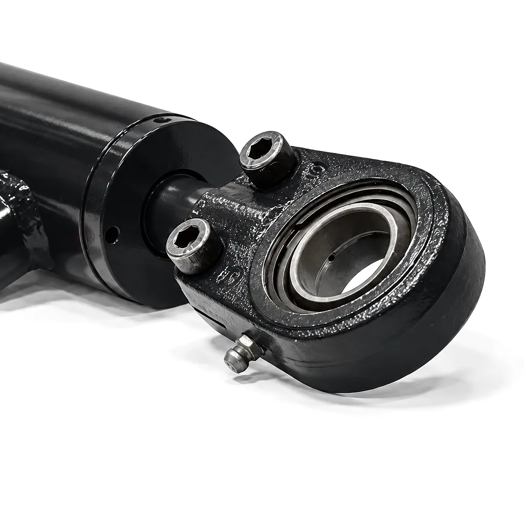 A structural steel fabrication business operating out of Sheffield’s Don Valley industrial corridor was experiencing recurring rod seal failures in the eight hydraulic press cylinders that form the core of their beam straightening line. The cylinders, running at 280 bar working pressure with a 12-hour continuous production shift pattern, were consuming an average of three complete seal replacement operations per month across the press bank. Each replacement required a four-hour production stoppage, amounting to twelve hours of lost press capacity monthly — at a direct cost the plant manager calculated at £18,000 per month in lost output and maintenance labour.
The original cylinder specification used a standard NBR rod seal set rated to 200 bar — a specification that had been adequate when the press line operated at 180 bar, but which became chronically insufficient when process intensification pushed working pressures to 280 bar eighteen months before the failure pattern emerged. The root cause was extrusion failure: at 280 bar, the NBR compound was cold-flowing into the 0.4 mm diametral clearance gap between the rod and the gland bush on every pressure stroke, generating extrusion debris that scored the chrome rod surface and produced the secondary abrasive wear that accelerated the deterioration.
Ever Power’s technical team conducted an on-site assessment of the press cylinders, reviewing the cylinder drawings, measuring the diametral clearances, and sampling the hydraulic fluid for contamination analysis. The solution delivered by Ever Power involved replacing the NBR rod seal with a polyurethane compact seal rated to 400 bar, adding a pair of PTFE back-up rings on both flanks of the static end-cap O-rings (upgraded to FKM), and re-specifying the gland bush clearance to 0.2 mm through the supply of precision-machined replacement gland bushes. The rod surface on two of the worst-affected cylinders was re-ground and re-chromed to eliminate the scoring that had developed. Following the Ever Power seal system upgrade, the Sheffield plant operated for eleven months without a single unplanned seal replacement — eliminating the recurring downtime entirely and recovering the full cost of the remediation within the first six weeks of operation.
“The diagnostic report Ever Power produced identified the exact failure mechanism we had been chasing for eighteen months. The upgraded PU seal specification combined with the back-up ring arrangement has transformed the reliability of our press line. Eleven months without a seal failure is a result we did not believe was achievable before this engagement.”
— Engineering Manager, Structural Steel Fabricator, Sheffield
“We were sceptical about a seal-only solution resolving a problem of this magnitude, but Ever Power’s reasoning was technically sound from the start. The FKM static O-rings they specified for our end-cap grooves have shown zero compression set at the eleven-month inspection — a dramatic contrast to the NBR seals we were replacing at three-month intervals.”
— Plant Maintenance Director, Heavy Pressing, South Yorkshire
“What distinguished Ever Power was the depth of the technical specification they produced — groove dimension drawings, back-up ring sizing rationale, surface finish targets — documentation that we could retain and use for future cylinder procurement. The lead time for the custom gland bushes was ten working days, which fitted our planned maintenance window precisely. Genuinely impressive supply chain coordination.”
— Procurement Manager, Industrial Machinery, West Yorkshire
Perguntas frequentes
Perguntas de engenheiros de compras industriais, gerentes de fábrica e equipes de manutenção do Reino Unido.
Pronto para especificar um sistema de vedação de cilindro hidráulico personalizado?
Compartilhe seus parâmetros operacionais com a equipe técnica da Ever Power e receba uma especificação completa da vedação, desenhos da geometria da ranhura e um orçamento competitivo em até 48 horas. Atendemos clientes industriais no Reino Unido, de Birmingham a Glasgow.
📧 Solicite um orçamento — [email protected]
Resposta em 24 horas · Especificações personalizadas · Serviço para o mercado do Reino Unido
editado por gzl
 Portuguese
  English
  Italian
  Dutch
Dutch  Swedish
  Danish
  Finnish
  Polish
  Hindi
Hindi  Kazakh
  Turkish
  Ukrainian
  Romanian
  Spanish
  German
  Russian
  Korean
  Japanese
  Vietnamese
  Thai
Thai  Indonesian
  Malay
Malay  French
  Greek
Greek