
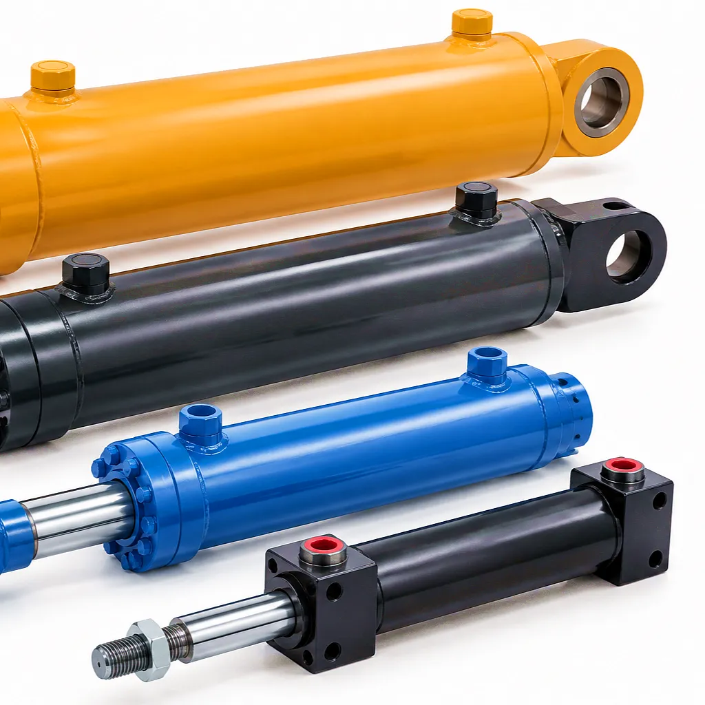
 Replacing a hydraulic boom cylinder is only half the job. The moment a new cylinder is installed, ambient air trapped inside the barrel, lines, and fittings becomes the single greatest threat to smooth, reliable operation. Air is compressible — hydraulic oil is not. Even a modest air pocket causes spongy response, unpredictable stroke speed, cavitation noise, and in severe cases, seal failure under repeated pressure cycling. For contractors running aerial work platforms, crane booms, or reach stackers across the UK’s dense construction and logistics corridors — from Birmingham’s Tyseley industrial estates to Sheffield’s advanced manufacturing parks — understanding how to properly bleed a hydraulic boom cylinder after replacement is not optional. It is the difference between a cylinder that delivers years of faultless service and one that fails within weeks, voiding its warranty and costing far more in downtime than the part itself.
Why Air Enters a Hydraulic Boom Cylinder System During Replacement
Open Line Exposure
Every time hydraulic hoses are disconnected, atmospheric air rushes into the open ports. Even brief exposure — during the swap of a failed cylinder on a mobile crane at a Manchester dockside operation — introduces enough air to cause immediate performance degradation. The volume of entrained air multiplies when both the port-A and port-B lines are left unplugged simultaneously, which happens routinely on tight deadlines.
Dry Cylinder Barrel
A new hydraulic boom cylinder arrives from the factory pre-tested but not pre-filled. The internal bore, piston seals, and rod surface are coated with a thin film of preservation oil — not full hydraulic fluid. When this cylinder is connected and pressurised for the first time, the entire internal air volume must be displaced. Failing to allow this displacement in a controlled way leads to pressure spikes as the pump attempts to compress the air column.
High-Point Accumulation
Hydraulic circuits on boom-type machinery — excavators, telehandlers, aerial lifts — often route hoses over structural members, creating high points where air naturally collects. When the cylinder is at the highest elevation in the circuit, gravity works against fluid fill. Air sits in the blind end of the barrel and refuses to migrate toward the tank unless the bleeding procedure specifically accounts for cylinder positioning during the purge cycle.
Inadequate Pre-Filling
Many technicians skip the step of manually filling the new cylinder before connection, assuming the system pump will do the work. In practice, the pump forces hydraulic fluid under pressure against a significant air column, causing turbulent mixing. This emulsified air-oil mixture is far harder to purge than a cleanly separated air pocket, and it degrades fluid quality by accelerating oxidation — a problem particularly relevant in the UK’s cold workshop temperatures during winter months.
Step-by-Step Procedure: Bleeding a Hydraulic Boom Cylinder After Replacement
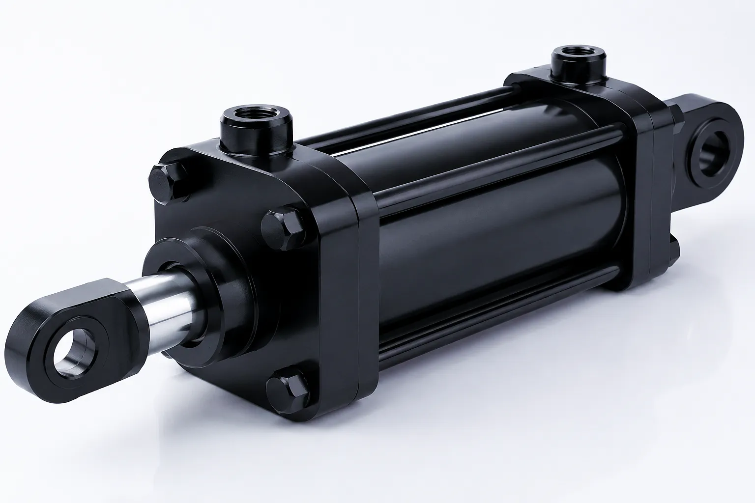
Isolate and Depressurise the System
Before touching any fitting, shut down the prime mover, engage the parking brake, and activate the hydraulic pressure-release valve if fitted. Turn the ignition key to the accessory position and cycle the control lever multiple times in each direction — this dissipates stored accumulator pressure. Wait a minimum of five minutes. Verify zero pressure using a calibrated gauge fitted to a service port. Never assume pressure is absent based on engine state alone; UK construction site incidents have repeatedly resulted from technicians working on apparently inactive circuits that retained residual charge in the accumulator or long hose runs.
Pre-Fill the New Cylinder Through the Port
Stand the new hydraulic boom cylinder vertically with the rod end up. Using a clean, lint-free funnel and fluid transfer pump, pour clean hydraulic fluid — matched to the machine specification, typically ISO VG 46 or ISO VG 68 — through the rod-end port until fluid emerges from the cap-end port. This ensures both chambers are fluid-filled before installation. This step alone eliminates the majority of air ingress at commissioning and significantly reduces the number of bleeder cycles required. Seal the ports immediately with clean plugs to prevent contamination. Ever Power ships all replacement cylinders with port plugs fitted as standard.
Connect Hoses — Fluid Running, Cap End First
Remove the cap-end port plug and connect the cap-end hose first, hand-tightening the fitting. Before connecting the rod-end hose, crack open the rod-end fitting slightly — this creates a bleed point. Slowly direct a small amount of fluid through the cap-end line until clean, bubble-free oil emerges from the cracked rod-end fitting. Tighten the rod-end fitting. This method — known as line-fill bleeding — prevents a pressure seal forming over a trapped air pocket. Use PTFE-rated fittings and torque all connections to the manufacturer’s specification; over-tightening JIC or BSP fittings on UK-spec machines is a common cause of micro-leaks that draw air back in over time.
Perform Low-Pressure Partial Stroke Cycles
Start the engine and allow hydraulic oil to reach operating temperature — at least 40°C, which may take 10–15 minutes on a cold Yorkshire morning. With the relief valve set below normal working pressure (if adjustable), slowly extend the boom cylinder to approximately 25% of full stroke and then retract fully. Repeat this partial cycle five to eight times without reaching the mechanical hard stops. Reaching the hard stop while air is still present drives peak pressure spikes that can damage the new seals before they have bedded in. At this stage, listen for irregular gurgling, observe the reservoir for surface turbulence or foam, and watch the boom movement for any jerkiness or hesitation.
Full-Stroke Cycling and Hard-Stop Bleeding
Once partial cycles show smooth movement and reservoir foam has settled, progressively increase stroke length to 50%, then 75%, and finally 100%. At full extension, hold the cylinder against the cushion for 5–10 seconds — this pressure-packs the remaining micro-bubbles into solution in the hydraulic fluid, where they are carried to the reservoir and released. Retract fully and hold for 5–10 seconds at the retracted position. Complete a minimum of five full-stroke cycles. Top up the reservoir to the correct level between each cycle pair, as bleeding displaces fluid into circuit components. Use only the same fluid grade and brand already in the system to avoid compatibility issues.
Use Bleed Screws Where Fitted
Many boom cylinders in the UK heavy plant market — particularly those on Liebherr, Terex, and Merlo machines operating in Lincolnshire agricultural fleets and West Midlands plant hire operations — are equipped with dedicated bleed screws on the cap end or at the highest circuit point. If present, crack the bleed screw one-quarter turn while the cylinder is pressurised in extension. Allow air and oil to weep out until a continuous, bubble-free oil stream emerges, then retighten to the specified torque. Bleed screws are single-use in some designs; if a copper crush washer is present, always replace it. Never overtighten, as stripping the bleed port thread requires barrel replacement in many monoblock cylinder designs.
Verify and Sign Off
After completing the bleed sequence, allow the machine to idle for five minutes and re-inspect all connection points for weeping. Check the reservoir level a final time and confirm it sits within the marked operating band. Perform one complete functional test — full extension under a representative load — and observe response time, drift rate, and noise. Document the bleed procedure in the machine service record; this is a requirement under UK PUWER regulations for plant in commercial use. Photograph the fitted cylinder, connection points, and reservoir level as part of a digital service file. Ever Power recommends a follow-up inspection at 20 operating hours to confirm no seepage and that reservoir foam has fully cleared.
Hydraulic Boom Cylinder — Technical Performance Parameters
The specification ranges below cover the standard Ever Power hydraulic boom cylinder range supplied to UK plant operators, crane builders, and OEM equipment manufacturers. Custom bore sizes, stroke lengths, mounting styles, and seal packages are available on request — contact the sales team for project-specific drawings and quotations.
Featured Boom Cylinder Products
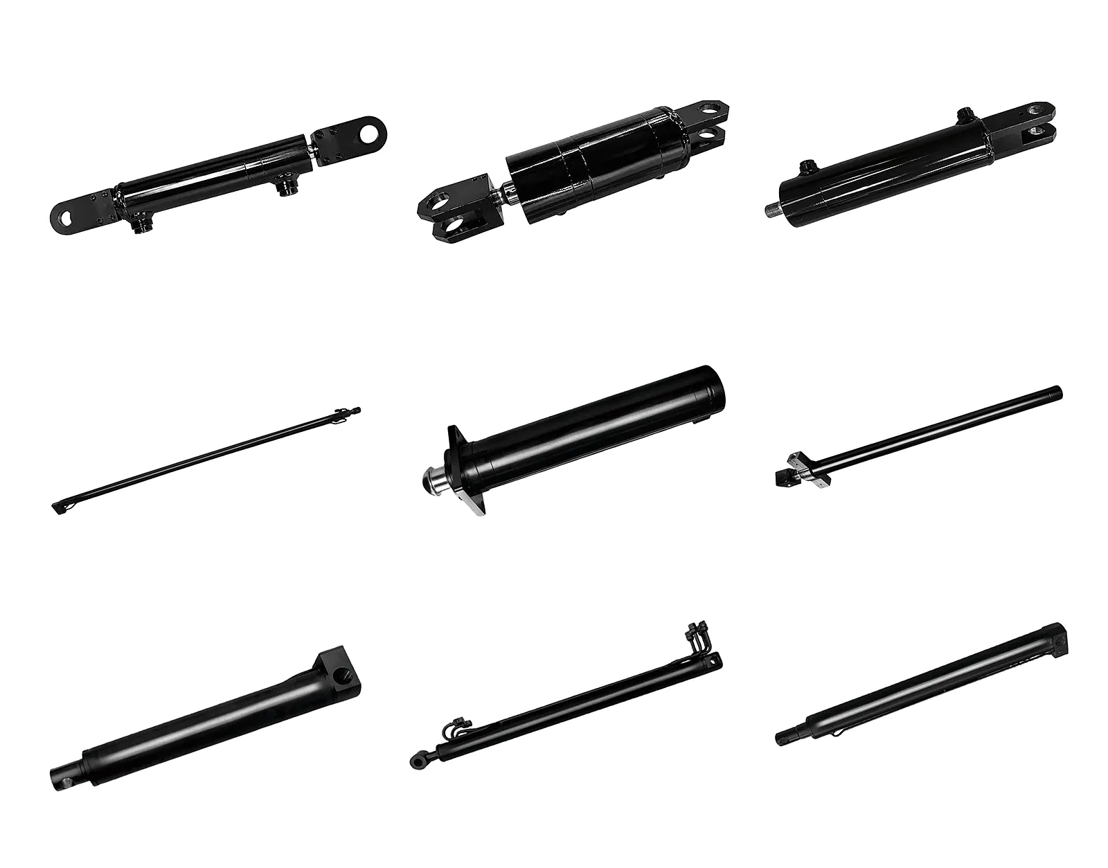
Frame Support Cylinder
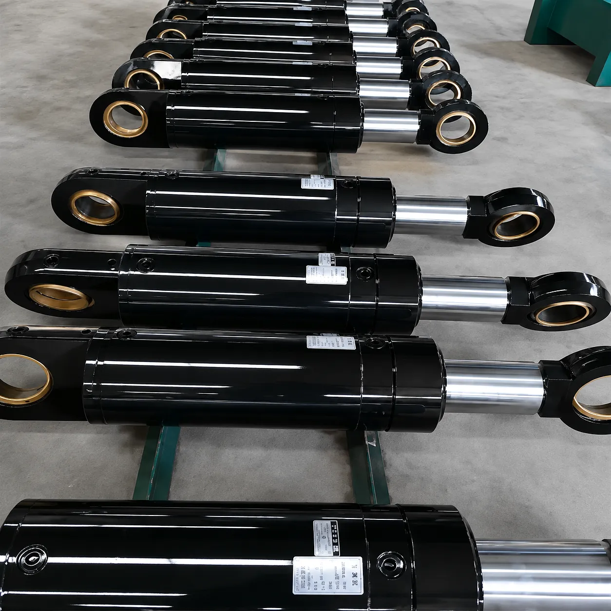
Engineered for structural load-bearing applications in boom assembly frames. The frame support cylinder provides consistent extension force across the full stroke range, with adjustable cushioning to protect frame welds during repeated cycling. Widely used on UK crane superstructures and offshore deck equipment.
Dış Destek Rafı Destek Silindiri
Designed specifically for outrigger stabilisation systems on mobile cranes, elevated work platforms, and heavy-lift vehicles. This cylinder’s precision bore tolerances and dual-seal rod design ensure zero drift under sustained static load — a critical requirement for LOLER-compliant operations throughout England, Scotland, and Wales.
How a Hydraulic Boom Cylinder Works — and Why Material Choice Determines Reliability
Operating Principle
The hydraulic boom cylinder operates on Pascal’s law: pressure applied at any point in a confined, incompressible fluid is transmitted equally in all directions. The pump generates flow; the directional control valve routes that flow to either the cap end (extending the rod) or the rod end (retracting it). The ratio of bore area to rod-annular area determines the force-speed balance. When the piston moves, one chamber fills while the other evacuates through the return line. Any air in either chamber acts as a spring, absorbing pressure and converting input energy into heat and vibration rather than useful mechanical work — which is why a thorough bleed procedure following replacement is so critical to restoring rated force output and stroke speed.
Varil Malzemesi
Ever Power sources ST52-3 and EN 10210 E355 seamless cold-drawn tube for all standard boom cylinder barrels. The tube is skived to a surface roughness of Ra 0.2–0.4 µm, then roller-burnished to Ra 0.1–0.2 µm. This mirror-quality bore surface reduces dynamic seal wear by up to 40% versus a honed-only surface and provides the smooth sliding contact needed for consistent speed control at low-flow rates. For salt-air environments along the UK coastline — offshore supply vessels operating from Aberdeen, or port equipment at Felixstowe — 316L stainless barrels with electropolished bores are supplied as a premium-grade option.
Rod Material and Chrome Layer
Piston rods are machined from CK45 or 42CrMo4 alloy steel, induction-hardened to a surface hardness of HRC 54–62, then hard-chrome plated to a minimum depth of 20 µm. The chrome surface resists corrosion from the moist, particulate-laden air common on UK construction sites through autumn and winter. After plating, each rod is ground and polished to h6 dimensional tolerance and a surface roughness of Ra 0.05–0.10 µm — the precision that allows polyurethane wiper seals to perform their dual role of scraping contaminants off the rod and retaining internal oil pressure over tens of thousands of stroke cycles.
Application Scenarios: Where Hydraulic Boom Cylinders Work in UK Industry
🏗
Construction: Mobile Cranes and Aerial Work Platforms
Mobile cranes working across Birmingham’s HS2 rail corridor and London’s ongoing regeneration projects depend on hydraulic boom cylinders to raise, angle, and extend jibs under multi-tonne suspended loads. The slew boom cylinder in a city-centre tower crane experiences millions of pressure cycles over its working life. Bore integrity, cushioning quality, and seal longevity — all directly influenced by the initial bleed quality — determine whether the machine meets its 10-year service plan or requires a costly mid-life cylinder replacement that disrupts a live construction programme.
🌿
Agriculture: Loader and Harvester Boom Arms
Farm machinery across the Yorkshire Dales and the East Anglian fen farms operates telehandler boom cylinders and articulated loader arms from pre-dawn through harvest season without interruption. When a boom cylinder seal fails during harvest and a replacement unit is fitted in the field, the bleed procedure must be completed with whatever tools the operator has available — typically in under an hour. Ever Power designs its agricultural-spec cylinders with accessible bleed screws as standard to make field commissioning practical even without a workshop environment or specialist hydraulic tooling.
🚤
Ports and Logistics: Reach Stackers and Ship-to-Shore Cranes
The major UK container ports at Felixstowe, Southampton, and Liverpool run reach stackers and rubber-tyred gantry cranes that handle thousands of container lifts daily. A hydraulic boom cylinder failure here stops container movement within minutes and creates a ripple effect across import logistics chains. Replacement cylinders must be bled and commissioned to full rated pressure in a single shift to minimise port disruption. The double-acting cylinder designs supplied by Ever Power to port equipment operators include pressure test certificates and material traceability documentation as standard.
⚒
Mining and Quarrying: Dump Truck Hoist Cylinders
Open-cast quarrying operations in Wales and the North Pennines use articulated dump trucks and rear-tipping haul wagons whose hoist cylinders operate at pressures up to 380 bar. The multi-stage telescopic boom cylinders on these vehicles are massive — some with 200 mm bore diameters and strokes exceeding 2,500 mm. The consequence of inadequate bleeding here is catastrophic: a single compressible air pocket under 380 bar of system pressure stores enormous energy, and its sudden release during a hard-stop contact can split cylinder barrels. The bleed procedure in this application demands patience and must be completed by a competent person under a documented risk assessment.
Customer Success Story: Sheffield Steelworks Crane Fleet Restoration
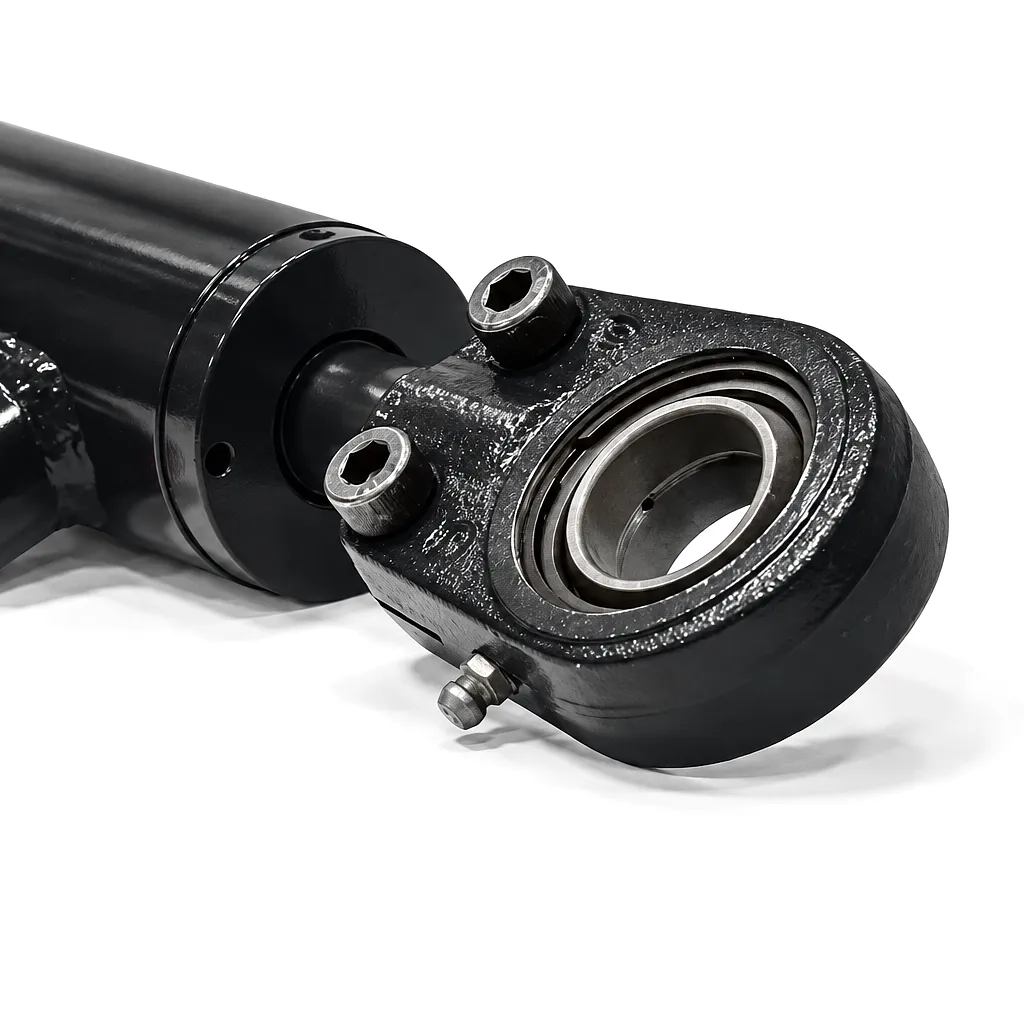
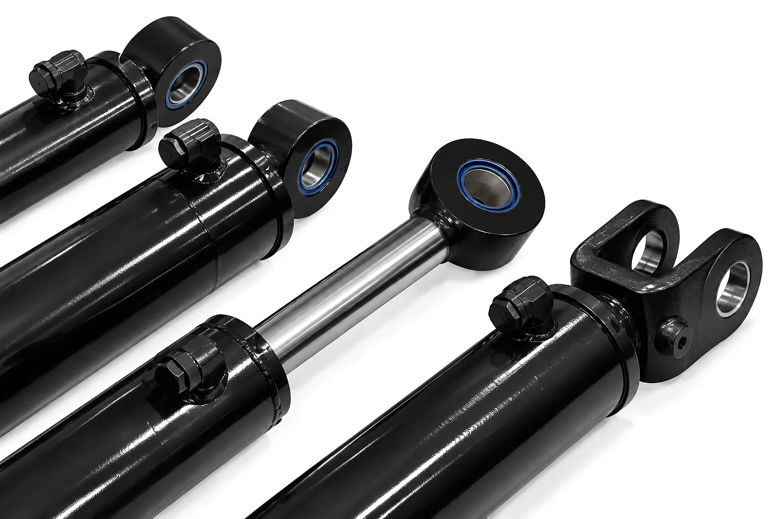 A major steel processing company operating an electric arc furnace facility in Sheffield’s Lower Don Valley contacted Ever Power following the sequential failure of three boom cylinder assemblies on their ladle transfer cranes over an 18-month period. The existing cylinders — sourced from a now-discontinued European supplier — had exhibited chronic rod seal weeping and erratic extension speed under hot-metal temperature conditions, where radiant heat from the ladle caused hydraulic fluid temperatures to exceed 110°C near the cylinder rod.
Ever Power’s technical team reviewed the crane manufacturer’s original hydraulic schematic, measured the failed cylinder dimensions on-site in Sheffield, and proposed a direct replacement specification using HNBR seal compounds rated to 150°C, stainless rod material with enhanced chrome layer thickness, and an additional external wiper seal to prevent metal dust ingress from the furnace environment. Three custom hydraulic boom cylinders were manufactured, pressure-tested to 400 bar, and despatched to Sheffield within 23 working days.
Following installation and a structured four-cycle bleed procedure coordinated remotely by Ever Power’s technical helpdesk, all three cranes returned to full-load transfer duty. At the 12-month follow-up review, zero seal failures had been recorded and rod surface condition remained within specification. The Sheffield facility subsequently placed an annual supply agreement with Ever Power covering four additional cylinder types across their crane fleet.
★★★★★
“The replacement boom cylinders for our Sheffield ladle cranes have now completed 14 months of continuous hot-metal service without a single seal issue. The HNBR seal package Ever Power specified has genuinely solved a problem we had been living with for years. The technical support during commissioning — particularly the bleed procedure guidance — was detailed and responsive.”
— Maintenance Manager, Steel Processing Facility, Sheffield, South Yorkshire
★★★★★
“We operate a mixed crane fleet across three UK sites and needed a supplier who could cross-reference multiple OEM drawings to produce replacement cylinders that install without modification. Ever Power delivered on this exactly. The dimensional accuracy of the rod journals and clevis bores meant we could fit and bleed the replacement cylinders inside a planned maintenance window — no fettling, no delays.”
— Fleet Engineering Director, Heavy Lift Contractor, Birmingham, West Midlands
★★★★★
“Price-competitive against domestic UK suppliers and significantly better quality on the surface finish side. The chrome layer on the replacement rods is measurably thicker and smoother than what came out of the machines originally. After following Ever Power’s bleed procedure exactly, the response speed on full stroke is noticeably more linear and predictable than it was before the failures started. Very happy with the whole experience.”
— Plant Manager, Quarrying and Aggregates Operation, County Durham, North East England
Troubleshooting: When the Bleed Procedure Does Not Fully Resolve Air Symptoms
Persistent Spongy Response After Full Bleeding
If spongy cylinder response persists after five or more complete bleed cycles, the source of air is likely continuous rather than residual. Suspect a suction leak at the pump inlet — common on machines where the reservoir tank inlet hose connection has deteriorated from age or UV exposure. A loose pump shaft seal also draws air under the negative pressure at the pump inlet. Check all suction-side connections by observing the reservoir surface during operation: continuous rapid surface bubbling, not just a brief period of settling foam, indicates live air ingestion rather than residual bleed-out air.
Cylinder Drift on Held Position
Cylinder drift — where the extended boom slowly lowers under load without command — is frequently misdiagnosed as an air-bleed failure. In practice, drift after a cylinder replacement points to the directional control valve or a counterbalance valve rather than the cylinder itself. Air in the cylinder would cause speed variation during movement, not position drift at rest. Verify by isolating the cylinder from the directional valve: if the cylinder holds position when the hydraulic lines are blocked at the valve body, the cylinder seals are sound and the valve is the source of drift.
Cavitation Noise on Retraction
A grinding or rattling sound during retraction — particularly at the start of the retraction stroke — indicates cavitation at the rod end. This happens when the retraction flow demand from the rod-end chamber exceeds the available fluid supply from the pump and return lines. The typical cause in a boom cylinder following replacement is an incorrect restriction in the rod-end return line, or a counterbalance valve set too high, starving the rod-end chamber of oil as the piston retracts. This is not an air problem — it is a flow problem — and should be addressed through valve adjustment rather than additional bleeding cycles.
Sıkça Sorulan Sorular
Need a Hydraulic Boom Cylinder for Your UK Operation?
Ever Power supplies custom and standard hydraulic cylinders to crane, construction, agriculture, and heavy plant operators across the United Kingdom. Fast lead times. Full material traceability. Competitive pricing.
📧 Get Your Quote: [email protected]
gzl tarafından düzenlendi
 Turkish
  English
  Italian
  Portuguese
  Dutch
Dutch  Swedish
  Danish
  Finnish
  Polish
  Hindi
Hindi  Kazakh
  Ukrainian
  Romanian
  Spanish
  German
  Russian
  Korean
  Japanese
  Vietnamese
  Thai
Thai  Indonesian
  Malay
Malay  French
  Greek
Greek