
Descrizione del prodotto
Standard Tie rod Hydraulic Cylinder
TR2008ASAE TR3008ASAE TR4008ASAE
Specificattions:
| Part Number | Rod Dia. | Bore x Stroke | Dimensions | Port Size | Pin Size | Weight (lbs) | |
| Retracted | Extended | ||||||
| GD TR25-2004 | 1 1/8” | 2”*4” | 14 1/4” | 18 1/4” | 3/8NPT | 1” | 15 |
| TR25-2006 | 2”*6” | 16 1/4” | 22 1/4” | 16 | |||
| TR25-2008 | 2”*8” | 18 1/4” | 26 1/4” | 18 | |||
| TR25-2008-ASAE | 2”*8” | 20 1/4” | 28 1/4” | 19 | |||
| TR25-2571 | 2”*10” | 20 1/4” | 30 1/4” | 19 | |||
| TR25-2012 | 2”*12” | 22 1/4” | 34 1/4” | 20 | |||
| TR25-2014 | 2”*14” | 24 1/4” | 38 1/4” | 22 | |||
| TR25-2016 | 2”*16” | 26 1/4” | 42 1/4” | 24 | |||
| TR25-2018 | 2”*18” | 28 1/4” | 46 1/4” | 26 | |||
| TR25-2571 | 2”*20” | 30 1/4” | 50 1/4” | 27 | |||
| TR25-2571 | 2”*24” | 34 1/4” | 58 1/4” | 30 | |||
| TR25-2030 | 2”*30” | 40 1/4” | 70 1/4” | 35 | |||
| TR25-2036 | 2”*36” | 46 1/4” | 82 1/4” | 40 | |||
| TR25-2504 | 1 1/8” | 2.5”*4” | 14 1/4” | 18 1/4” | 3/8NPT | 1” | 18 |
| TR25-2506 | 2.5”*6” | 16 1/4” | 22 1/4” | 20 | |||
| TR25-2508 | 2.5”*8” | 18 1/4” | 26 1/4” | 22 | |||
| TR25-2508-ASAE | 2.5”*8” | 20 1/4” | 28 1/4” | 22 | |||
| TR25-2510 | 2.5”*10” | 20 1/4” | 30 1/4” | 23 | |||
| TR25-2512 | 2.5”*12” | 22 1/4” | 34 1/4” | 25 | |||
| TR25-2514 | 2.5”*14” | 24 1/4” | 38 1/4” | 27 | |||
| TR25-2516 | 2.5”*16” | 26 1/4” | 42 1/4” | 28 | |||
| TR25-2518 | 2.5”*18” | 28 1/4” | 46 1/4” | 29 | |||
| TR25-2520 | 2.5”*20” | 30 1/4” | 50 1/4” | 31 | |||
| TR25-2524 | 2.5”*24” | 34 1/4” | 58 1/4” | 35 | |||
| TR25-2530 | 2.5”*30” | 40 1/4” | 70 1/4” | 45 | |||
| TR25-2536 | 2.5”*36” | 46 1/4” | 82 1/4” | 50 | |||
| TR25-3004 | 1 1/4” | 3”*4” | 14 1/4” | 18 1/4” | 1/2NPT | 1” | 22 |
| TR25-3006 | 3”*6” | 16 1/4” | 22 1/4” | 24 | |||
| TR25-3008 | 3”*8” | 18 1/4” | 26 1/4” | 26 | |||
| TR25-3008-ASAE | 3”*8” | 20 1/4” | 28 1/4” | 27 | |||
| TR25-3571 | 3”*10” | 20 1/4” | 30 1/4” | 28 | |||
| TR25-3012 | 3”*12” | 22 1/4” | 34 1/4” | 31 | |||
| TR25-3014 | 3”*14” | 24 1/4” | 38 1/4” | 33 | |||
| TR25-3016 | 3”*16” | 26 1/4” | 42 1/4” | 35 | |||
| TR25-3016-ASAE | 3”*16” | 31 1/4” | 47 1/4” | 1 1/4” | 38 | ||
| TR25-3018 | 1 1/2” | 3”*18” | 28 1/4” | 46 1/4” | 1” | 42 | |
| TR25-3571 | 3”*20” | 30 1/4” | 50 1/4” | 44 | |||
| TR25-3571 | 3”*24” | 34 1/4” | 58 1/4” | 49 | |||
| TR25-3030 | 3”*30” | 40 1/4” | 70 1/4” | 58 | |||
| GD-TR25-3036 | 3”*36” | 46 1/4” | 82 1/4” | 67 | |||
| TR25-3504 | 1 1/4” | 3.5”*4” | 14 1/4” | 18 1/4” | 1/2NPT | 1” | 29 |
| TR25-3506 | 3.5”*6” | 16 1/4” | 22 1/4” | 30 | |||
| TR25-3508 | 3.5”*8” | 18 1/4” | 26 1/4” | 34 | |||
| TR25-3508-ASAE | 3.5”*8” | 20 1/4” | 28 1/4” | 35 | |||
| TR25-3510 | 3.5”*10” | 20 1/4” | 30 1/4” | 37 | |||
| TR25-3512 | 3.5”*12” | 22 1/4” | 34 1/4” | 39 | |||
| TR25-3514 | 3.5”*14” | 24 1/4” | 38 1/4” | 42 | |||
| TR25-3516 | 3.5”*16” | 26 1/4” | 42 1/4” | 44 | |||
| TR25-3516-ASAE | 1 1/2” | 3.5”*16” | 31 1/4” | 47 1/4” | 1 1/4” | 50 | |
| TR25-3518 | 1 1/4” | 3.5”*18” | 28 1/4” | 46 1/4” | 1” | 47 | |
| TR25-3520 | 3.5”*20” | 30 1/4” | 50 1/4” | 49 | |||
| TR25-3524 | 1 1/2” | 3.5”*24” | 34 1/4” | 58 1/4” | 58 | ||
| TR25-3530 | 3.5”*30” | 40 1/4” | 70 1/4” | 70 | |||
| TR25-3536 | 3.5”*36” | 46 1/4” | 82 1/4” | 72 | |||
| TR25-4004 | 1 1/4” | 4”*4” | 14 1/4” | 18 1/4” | 1/2NPT | 1” | 33 |
| TR25-4006 | 4”*6” | 16 1/4” | 22 1/4” | 36 | |||
| TR25-4008 | 4”*8” | 18 1/4” | 26 1/4” | 39 | |||
| TR25-4008-ASAE | 4”*8” | 20 1/4” | 28 1/4” | 41 | |||
| TR25-4571 | 4”*10” | 20 1/4” | 30 1/4” | 42 | |||
| TR25-4012 | 4”*12” | 22 1/4” | 34 1/4” | 45 | |||
| GD-TR25-4014 | 4”*14” | 24 1/4” | 38 1/4” | 47 | |||
| TR25-4016 | 4”*16” | 26 1/4” | 42 1/4” | 49 | |||
| TR25-4016-ASAE | 2” | 4”*16” | 31 1/4” | 47 1/4” | 1 1/4” | 63 | |
| TR25-4018 | 1 1/2” | 4”*18” | 28 1/4” | 46 1/4” | 1” | 55 | |
| TR25-4571 | 4”*20” | 30 1/4” | 50 1/4” | 58 | |||
| TR25-4571-150 | 4”*24” | 34 1/4” | 58 1/4” | 64 | |||
| TR25-4571-175 | 1 3/4” | 4”*24” | 34 1/4” | 58 1/4” | 68 | ||
| TR25-4571-200 | 2” | 4”*24” | 34 1/4” | 58 1/4” | 73 | ||
| TR25-4030 | 4”*30” | 40 1/4” | 70 1/4” | 84 | |||
| TR25-4036 | 4”*36” | 46 1/4” | 82 1/4” | 95 | |||
| TR25-5004 | 1 1/2” | 5”*4” | 16 1/4” | 20 1/4” | 1/2NPT | 1” | 53 |
| GD-TR25-5006 | 5”*6” | 18 1/4” | 24 1/4” | 55 | |||
| TR25-5008 | 5”*8” | 20 1/4” | 28 1/4” | 64 | |||
| TR25-5571 | 5”*10” | 22 1/4” | 32 1/4” | 68 | |||
| TR25-5012 | 2” | 5”*12” | 24 1/4” | 36 1/4” | 77 | ||
| TR25-5014 | 5”*14” | 26 1/4” | 40 1/4” | 82 | |||
| TR25-5016 | 5”*16” | 28 1/4” | 44 1/4” | 87 | |||
| TR25-5016-ASAE | 5”*16” | 31 1/4” | 47 1/4” | 1 1/4” | 90 | ||
| TR25-5018 | 5”*18” | 30 1/4” | 48 1/4” | 1” | 92 | ||
| TR25-5571 | 5”*20” | 32 1/4” | 52 1/4” | 96 | |||
| TR25-5571 | 5”*24” | 36 1/4” | 60 1/4” | 106 | |||
| TR25-5030 | 5”*30” | 42 1/4” | 72 1/4” | 121 | |||
| GD-TR25-5036 | 5”*36” | 48 1/4” | 84 1/4” | 136 | |||
| PART NUMBER | INSIDER DIAMETER | OUTSIDER DIAMETER | *A | B | *C | *D | *E | F | G | H | 1 | *J | ROD THREAD | PORT |
| TR2.5-20- | 2.00″ | 2.37″ | 10.25″ | 2.00″ | 1.01″ | 2.00″ | 3.75″ | 2.25n | 1.12″ | 2.06″ | 2.12″ | 2.62″ | 1.125-12 UNF | 3/8-NPT |
| TR2.5-25- | 2.50″ | 2.87″ | 10.25″ | 2.00″ | 1.01″ | 2.25″ | 3.75″ | 2.25″ | 1.12″ | 2.06″ | 2.12″ | 2.62″ | 1.125-12 UNF | 3/8-NPT |
| TR2.5-30- | 3.00″ | 3.37″ | 10.25″ | 2.00″ | 1.01″ | 2.25″ | 3.75″ | 2.25″ | 1.12″ | 2.06″ | 2.12″ | 2.62″ | 1.250-12 UNF | 1/2-NPT |
| TR2.5-35- | 3.50″ | 3.87″ | 10.25″ | 2.00″ | 1.01″ | 2.25″ | 3.62″ | 2.50″ | 1.12″ | 2.06″ | 2.12″ | 2.62″ | 1.250-12 UNF | 1/2-NPT |
| TR2.5-40- | 4.00″ | 4.37″ | 10.25″ | 2.25″ | 1.01″ | 2.25″ | 3.56″ | 2.62″ | 1.12″ | 2.06″ | 2.12″ | 2.62″ | 1.250-12 UNF | 1/2-NPT |
| TR2.5-50- | 5.00″ | 5.37″ | 12.25″ | 2.87″ | 1.26″ | 2.75″ | 4.18″ | 3.50″ | 1.12″ | 2.25″ | 2.12″ | 3.31″ | 1.500-12 UNF | 1/2-NPT |
| *FOR 8.00″ ASAE STROKE :*A= 12.25n AND FOR 16.00″ ASAE STROKE:*A= 15.50″ | ||||||||||||||
| *FOR 8.00″ STROKE :*E= 5.75″(2.0(T TO 3.00″ BORE) *E= 5.62n(3.50″ BORE) *E = 5.56″(4.0(T BORE) | ||||||||||||||
| *FOR 16.00″ ASAE STROKE: *E = 9.00″(2.00″ TO 3.00B BORE) *E = 8.87″(3.50″ BORE) *E = 8.81″(4.00″ BORE) | ||||||||||||||
| *FOR TTR2.5-2518 TO TTR2.5-2536: ROD THREAD= 1.125-12 UNF | ||||||||||||||
| *FOR TTR2.5-4016-ASAE TO TR2.5-4036:*D= 2.50″ *J = 2.75″ *RODTHREAD= 1.500-12 UNF | ||||||||||||||
| *FOR 16.00’ASAE STROKE:*C = 1.26* | ||||||||||||||
| SEAL TEMPERATURE RANGE: -30°C/+100°C(-22°F/+212°F) | ||||||||||||||
| SEAL MAXIMUM SPEED:3 FT/SEC | ||||||||||||||
| MAXIMUM RETRACTED WORKING PRESSURE= 2500 PSI | ||||||||||||||
| DIMENSIONS A AND E ARE FOR REFERENCES ONLY AS CLEVIS IS ADJUSTABLE | ||||||||||||||
Confezione
We use metal case/plywood case /carton or as Customer’s requirements
Delivery time:30-40 days
Hydraulic cylinders can be built according to your drawings or technical requirement.
Sample order are acceptable.
| Certificazione: | GS, RoHS, CE, ISO9001 |
|---|---|
| Pressione: | Medium Pressure |
| Temperatura di esercizio: | Normal Temperature |
| Samples: | US$ 30/Piece 1 Piece(Min.Order) | Order Sample |
|---|
| Personalizzazione: | Disponibile |
|
|---|
.shipping-cost-tm .tm-status-off{background: none;padding:0;color: #1470cc}
| Shipping Cost: Estimated freight per unit. | about shipping cost and estimated delivery time. |
|---|
| Payment Method: |
|
|---|---|
| Initial Payment Full Payment |
| Currency: | US$ |
|---|
| Return&refunds: | You can apply for a refund up to 30 days after receipt of the products. |
|---|
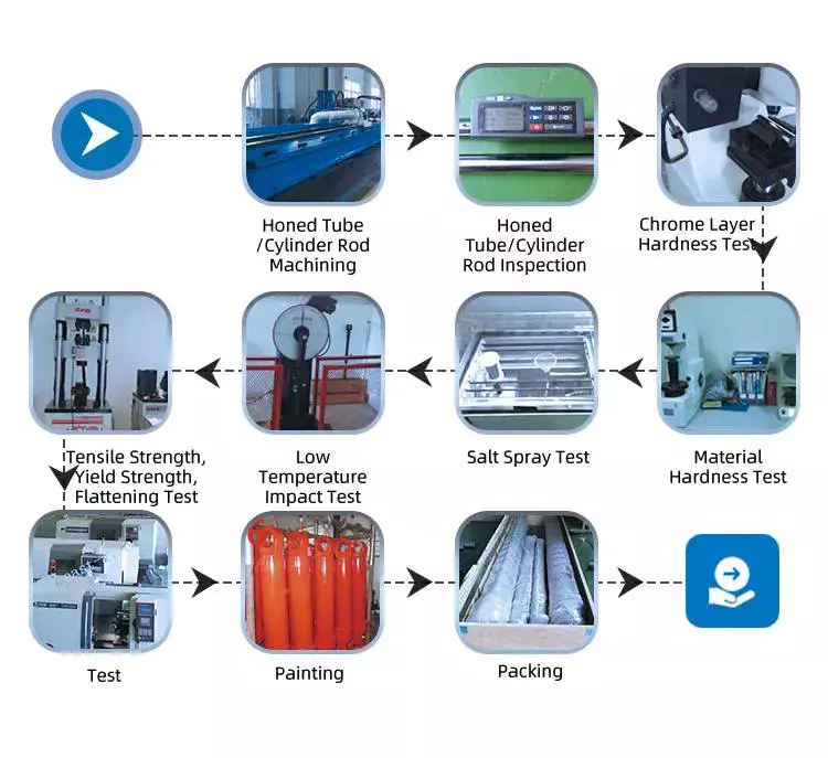
How do hydraulic cylinders handle variations in temperature and harsh operating environments?
Hydraulic cylinders are designed to handle variations in temperature and harsh operating environments by incorporating specific features and materials that ensure their durability, reliability, and performance. The ability of hydraulic cylinders to withstand extreme temperatures, corrosive environments, and other harsh conditions is crucial for their successful operation in a wide range of applications. Here’s a detailed explanation of how hydraulic cylinders handle variations in temperature and harsh operating environments:
1. Temperature Range:
– Hydraulic cylinders are designed to operate within a specified temperature range. The materials used in their construction, such as cylinder barrels, pistons, seals, and lubricants, are selected to withstand the anticipated temperature variations. Specialized seals and O-rings made from materials like nitrile, Viton, or polyurethane are used to maintain their sealing properties over a wide temperature range. Heat-resistant coatings or thermal insulation may be applied to certain components to protect them from high temperatures.
2. Thermal Expansion:
– Hydraulic cylinders are designed to accommodate thermal expansion and contraction that occurs with temperature changes. The materials used in their construction have different coefficients of thermal expansion, allowing the cylinder components to expand or contract at a similar rate. This design consideration prevents excessive stress, binding, or leakage that could result from thermal expansion or contraction.
3. Heat Dissipation:
– In applications where hydraulic cylinders are subjected to high temperatures, heat dissipation mechanisms are employed to prevent overheating. Cooling fins or heat sinks may be incorporated into the cylinder design to increase the surface area for heat transfer. In some cases, external cooling methods such as air or liquid cooling systems can be used to maintain optimal operating temperatures.
4. Corrosion Resistance:
– Hydraulic cylinders used in harsh operating environments are constructed from materials that exhibit excellent corrosion resistance. Stainless steel, chrome-plated steel, or other corrosion-resistant alloys are commonly used for cylinder components exposed to corrosive substances or environments. Additionally, surface treatments such as coatings, plating, or specialized paints can provide an extra layer of protection against corrosion.
5. Sealing Systems:
– Hydraulic cylinders employ sealing systems that are specifically designed to withstand harsh operating environments. The seals used in hydraulic cylinders are selected based on their resistance to temperature extremes, chemicals, abrasion, and other environmental factors. Specialized seal designs, such as wiper seals, rod seals, or high-temperature seals, are utilized to maintain effective sealing and prevent contamination of the hydraulic fluid.
6. Lubrication:
– Proper lubrication is essential for the smooth operation and longevity of hydraulic cylinders, particularly in harsh operating environments. Lubricants are selected based on their ability to withstand high temperatures, resist oxidation, and provide effective lubrication under extreme conditions. Regular maintenance and lubrication practices ensure that the cylinder components continue to operate smoothly and reduce the effects of wear and friction.
7. Robust Construction:
– Hydraulic cylinders designed for harsh operating environments are built with robust construction techniques to withstand the rigors of such conditions. The cylinder barrels, rods, and other components are manufactured to meet strict quality and durability standards. Welded or bolted construction methods are employed to ensure the structural integrity of the cylinders. Reinforcements, such as flanges or tie rods, may be added to enhance the cylinder’s strength and resistance to external forces.
8. Environmental Protection:
– Hydraulic cylinders can be equipped with additional protective features to shield them from harsh operating environments. Protective covers, boots, or bellows can be used to prevent contaminants, debris, or moisture from entering the cylinder and compromising its performance. These protective measures help extend the service life of hydraulic cylinders in demanding conditions.
9. Compliance with Standards:
– Hydraulic cylinders manufactured for specific industries or applications often comply with industry standards or regulations related to operating temperature ranges, environmental conditions, or safety requirements. Compliance with these standards ensures that hydraulic cylinders are designed and tested to meet the specific demands of their intended operating environments.
In summary, hydraulic cylinders are designed to handle variations in temperature and harsh operating environments by incorporating suitable materials, thermal expansion considerations, heat dissipation mechanisms, corrosion-resistant components, specialized sealing systems, proper lubrication, robust construction techniques, protective features, and compliance with industry standards. These design considerations and features enable hydraulic cylinders to operate reliably and effectively in a wide range of demanding applications and environmental conditions.
Gestione delle sfide poste dalle diverse viscosità dei fluidi nei cilindri idraulici
I cilindri idraulici sono progettati per affrontare le sfide poste dalle diverse viscosità dei fluidi. La viscosità del fluido idraulico può variare in base alla temperatura, al tipo di fluido utilizzato e ad altri fattori. I sistemi idraulici devono essere in grado di gestire queste variazioni per garantire prestazioni ed efficienza ottimali. Vediamo come i cilindri idraulici gestiscono le sfide poste dalle diverse viscosità dei fluidi:
- Selezione del fluido: I cilindri idraulici sono progettati per funzionare con una vasta gamma di fluidi idraulici, ognuno con le proprie specifiche caratteristiche di viscosità. La scelta di un fluido appropriato con la viscosità desiderata è fondamentale per garantire prestazioni ottimali. I produttori forniscono linee guida relative all'intervallo di viscosità raccomandato per specifici sistemi e cilindri idraulici. Scegliendo il fluido giusto, i cilindri idraulici possono affrontare efficacemente le sfide poste dalle diverse viscosità dei fluidi.
- Compensazione della viscosità: I sistemi idraulici spesso integrano caratteristiche per compensare le variazioni di viscosità del fluido. Ad esempio, alcuni sistemi idraulici utilizzano valvole di compensazione della pressione che regolano la portata in base alla viscosità del fluido. Questa compensazione garantisce prestazioni costanti in diverse condizioni operative e con diverse viscosità del fluido. I cilindri idraulici lavorano in sinergia con questi meccanismi di compensazione per mantenere precisione e controllo, indipendentemente dalla viscosità del fluido.
- Controllo della temperatura: La viscosità dei fluidi dipende fortemente dalla temperatura. I cilindri idraulici utilizzano diversi meccanismi di controllo della temperatura per affrontare le problematiche poste dalle variazioni di viscosità indotte dalla temperatura. Scambiatori di calore, refrigeratori e valvole termostatiche sono comunemente impiegati per regolare la temperatura del fluido idraulico all'interno del sistema. Controllando la temperatura del fluido, i cilindri idraulici possono mantenere l'intervallo di viscosità desiderato, garantendo un funzionamento affidabile ed efficiente.
- Filtrazione efficiente: I contaminanti presenti nel fluido idraulico possono influenzarne la viscosità e le prestazioni complessive. I sistemi idraulici incorporano efficienti sistemi di filtrazione per rimuovere particelle e impurità dal fluido. Un fluido pulito con la viscosità appropriata garantisce un funzionamento ottimale dei cilindri idraulici. La manutenzione regolare e la sostituzione dei filtri sono essenziali per mantenere la viscosità del fluido desiderata e prevenire problemi legati alla contaminazione del fluido stesso.
- Lubrificazione adeguata: Le diverse viscosità dei fluidi possono influenzare le proprietà di lubrificazione all'interno dei cilindri idraulici. La lubrificazione è essenziale per ridurre al minimo l'attrito e l'usura tra le parti in movimento. I sistemi idraulici utilizzano lubrificanti specificamente formulati per l'intervallo di viscosità del fluido previsto. Una lubrificazione adeguata garantisce un funzionamento regolare e prolunga la durata dei cilindri idraulici, anche in presenza di viscosità del fluido variabili.
In sintesi, i cilindri idraulici impiegano diverse strategie per affrontare le problematiche associate alle diverse viscosità dei fluidi. Selezionando fluidi appropriati, integrando meccanismi di compensazione della viscosità, controllando la temperatura, implementando una filtrazione efficiente e garantendo una lubrificazione adeguata, i cilindri idraulici possono adattarsi alle variazioni di viscosità del fluido. Queste misure consentono ai sistemi idraulici di offrire prestazioni costanti, un controllo preciso e un funzionamento efficiente in un ampio intervallo di viscosità del fluido.
What safety precautions should be followed when working with hydraulic cylinders?
Working with hydraulic cylinders requires strict adherence to safety precautions to prevent accidents, injuries, and damage to equipment or property. Hydraulic systems operate under high pressures and involve moving parts, which can pose serious hazards if not handled properly. Here’s a detailed explanation of the safety precautions that should be followed when working with hydraulic cylinders:
1. Training and Knowledge:
– Ensure that personnel working with hydraulic cylinders have received adequate training and possess a thorough understanding of hydraulic system operation, maintenance, and safety protocols. Proper training should cover topics such as hydraulic principles, pressure ratings, safe work practices, and emergency procedures. Only trained and authorized personnel should be allowed to handle hydraulic cylinders.
2. Wear Personal Protective Equipment (PPE):
– Always wear appropriate personal protective equipment when working with hydraulic cylinders. This may include safety glasses, gloves, protective clothing, and steel-toed boots. PPE helps protect against potential hazards, such as hydraulic fluid leaks, flying debris, or accidental contact with moving parts.
3. Hydraulic System Inspection:
– Before working with hydraulic cylinders, inspect the entire hydraulic system for any signs of damage, leaks, or loose connections. Check hydraulic hoses, fittings, valves, and cylinders for integrity and secure fastening. If any issues are detected, the system should be repaired or serviced before operation.
4. Relieve Pressure:
– Before performing any maintenance or disassembly on a hydraulic cylinder, it is crucial to relieve the pressure in the system. Follow the manufacturer’s instructions to properly release pressure and ensure that the hydraulic cylinder is depressurized before starting any work. Failure to do so can result in sudden and uncontrolled movement of the cylinder or hydraulic lines, leading to serious injuries.
5. Lockout/Tagout Procedures:
– Implement lockout/tagout procedures to prevent accidental energization of the hydraulic system while maintenance or repair work is being conducted. Lockout/tagout involves isolating the energy source, such as shutting off the hydraulic pump and locking or tagging the controls to prevent unauthorized operation. This procedure ensures that the hydraulic cylinder remains in a safe, non-operational state during maintenance activities.
6. Use Proper Lifting Techniques:
– When working with heavy hydraulic cylinders or components, use proper lifting techniques and equipment to avoid strain or injury. Hydraulic cylinders can be heavy and awkward to handle, so ensure that lifting equipment, such as cranes or hoists, is properly rated and used correctly. Follow safe lifting practices, including securing the load and maintaining a stable lifting posture.
7. Hydraulic Fluid Handling:
– Handle hydraulic fluid with care and follow proper procedures for fluid filling, transfer, and disposal. Avoid contact with the skin or eyes, as hydraulic fluid may be hazardous. Use appropriate containers and equipment to prevent spills or leaks. If any hydraulic fluid comes into contact with the skin or eyes, rinse thoroughly with water and seek medical attention if necessary.
8. Regular Maintenance:
– Perform regular maintenance and inspections on hydraulic cylinders to ensure their safe and reliable operation. This includes checking for leaks, inspecting seals, monitoring fluid levels, and conducting periodic servicing as recommended by the manufacturer. Proper maintenance helps prevent unexpected failures and ensures the continued safe use of hydraulic cylinders.
9. Follow Manufacturer Guidelines:
– Always follow the manufacturer’s guidelines, instructions, and recommendations for the specific hydraulic cylinders and equipment being used. Manufacturers provide important safety information, maintenance schedules, and operational guidelines that should be strictly adhered to for safe and optimal performance.
10. Emergency Preparedness:
– Be prepared for potential emergencies by having appropriate safety equipment, such as fire extinguishers, first aid kits, and emergency eyewash stations, readily available. Establish clear communication channels and emergency response procedures to promptly address any accidents, leaks, or injuries that may occur during hydraulic cylinder operations.
By following these safety precautions, individuals working with hydraulic cylinders can minimize the risk of accidents, injuries, and property damage. It is essential to prioritize safety, maintain awareness of potential hazards, and ensure compliance with relevant safety regulations and industry standards.


editor by CX 2023-10-28
 Italian
  English
  Portuguese
  Dutch
Dutch  Swedish
  Danish
  Finnish
  Polish
  Hindi
Hindi  Kazakh
  Turkish
  Ukrainian
  Romanian
  Spanish
  German
  Russian
  Korean
  Japanese
  Vietnamese
  Thai
Thai  Indonesian
  Malay
Malay  French
  Greek
Greek