
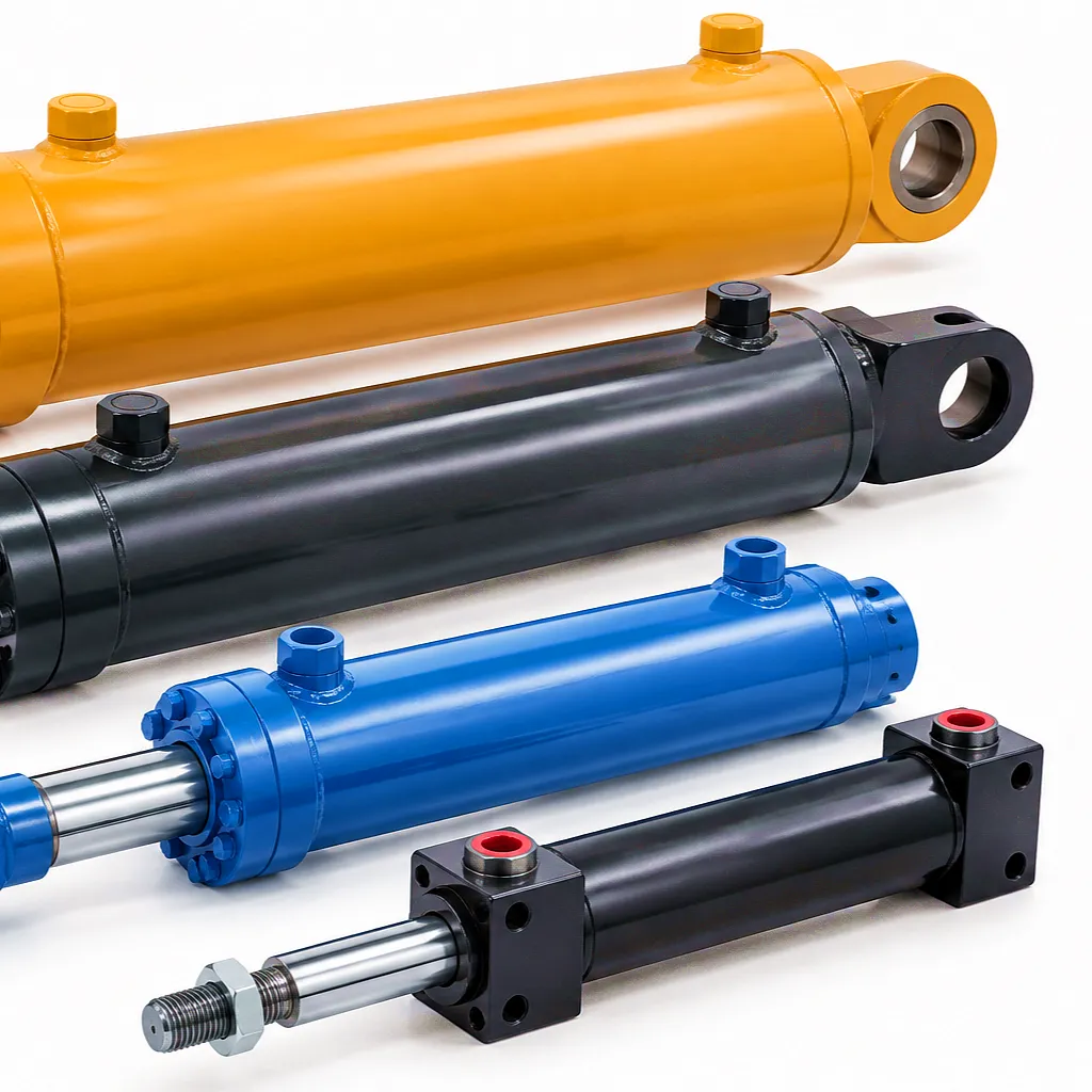
The Bore Diameter: Force, Pressure, and Why Every Millimetre Counts
When you increase the bore of a boom hydraulic cylinder from 100 mm to 120 mm, the piston area grows from 7,854 mm² to 11,310 mm² — an increase of 44 per cent. At a working pressure of 250 bar, that shift in bore alone lifts the theoretical push force from 196 kN to 283 kN, without touching any other variable. This is why procurement teams sourcing cylinders for heavy demolition attachments in Birmingham or heavy-plate press lines in the West Midlands must be precise about bore selection. An under-bored cylinder running near its pressure relief threshold runs hot, shortens seal life dramatically, and risks rod-end buckling under shock loads. An over-bored unit wastes pump capacity, increases oil volume, slows cycle times, and adds unnecessary mass to the machine frame.
In practice, bore selection also determines the wall thickness needed in the barrel, the grade of steel required, and the honing tolerances that govern seal performance. Ever Power manufactures cylinder barrels from cold-drawn seamless steel tube to DIN EN 10305-1 standards, honed to Ra 0.2–0.4 µm surface roughness internally. This tolerance band matches the lip geometry of polyurethane and NBR composite seals to their designed contact stress, keeping leakage to under 0.5 cm³/min at 350 bar working pressure. When you read a bore figure on an Ever Power data sheet, you are reading the post-hone finished diameter, not the raw tube bore — a distinction that matters significantly when comparing quotes from different suppliers in the market.
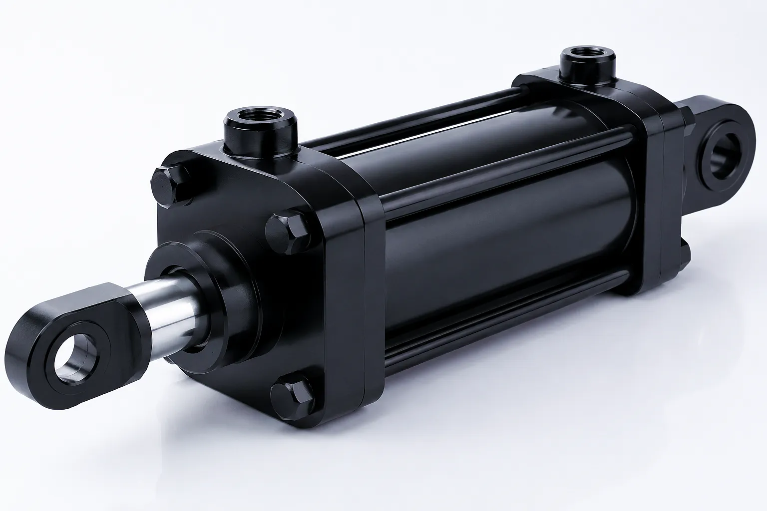
Stroke Length: Travel, Volume, and Speed — What the Second Number Tells You
The stroke length is the linear distance the cylinder rod travels from its fully retracted closed length to its fully extended position. On an excavator boom arm, this might be 1,250 mm. On a compact loader lift cylinder, it might be 580 mm. On a bespoke forestry crane working the Highland timber circuits in Scotland, it could be a non-standard 1,640 mm dictated purely by the geometric sweep of the boom pivot. Reading the stroke number means understanding several downstream consequences simultaneously: the volume of hydraulic oil consumed per cycle, the speed of extension and retraction at a given pump flow rate, the rod diameter required to resist buckling at full extension, and the closed length constraint imposed by the machine frame envelope.
Oil volume per stroke is calculated as bore area multiplied by stroke length — a 100 mm bore cylinder with a 1,000 mm stroke displaces 7.85 litres on the cap end per cycle. At a pump flow of 60 litres per minute, that stroke takes 7.85 seconds, which defines the cycle time your operator experiences. Increasing stroke length at the same bore and flow slows the machine; increasing bore at the same stroke and flow also slows it. This interdependency is why boom cylinder specifications cannot be changed in isolation. UK plant hire companies face this challenge when respecifying machines from European OEM drawings where metric standards differ subtly from British legacy equipment dimensions — a 4-inch bore is not 100 mm; it is 101.6 mm, and that gap matters for seal sourcing.
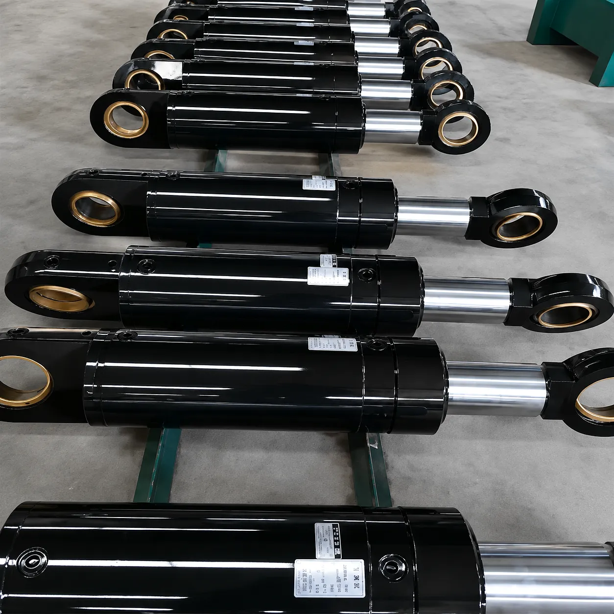
How a Boom Cylinder Converts Fluid Pressure Into Linear Force: The Working Principle
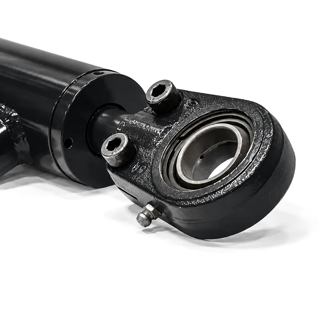 A boom hydraulic cylinder is a double-acting linear actuator that converts pressurised hydraulic fluid into controlled linear motion and force. Oil supplied by the machine’s hydraulic pump enters the cap-end port and acts against the full bore area of the piston, generating the extension force used to lift or push the boom. When the control valve shifts to retract, oil is directed to the rod-end port and acts on the annular area of the piston — the bore area minus the rod area — creating the retraction force needed to pull the boom back. The difference between cap-end and rod-end force at the same pressure is determined entirely by the rod diameter relative to the bore, which is why the rod-to-bore ratio is a critical design parameter that sits alongside the bore and stroke figures in every serious specification document.
The cylinder barrel, end caps, piston, and rod form a sealed pressure vessel that must withstand not just the rated working pressure but repeated dynamic pressure spikes — commonly 1.3 to 1.5 times working pressure — generated by shock loading on the boom structure when a bucket strikes hard ground or a clamshell attachment impacts a rock face. This is why cylinder burst pressure ratings, typically 2× working pressure for standard grade units and 2.5× for heavy-duty variants, matter as much as the bore and stroke data when comparing competing suppliers’ datasheets. The 油圧式回転アクチュエータステアリングシリンダー range from Ever Power also follows these same pressure-rating disciplines, ensuring consistent safety margins across the full actuator family.
Core Materials in Boom Hydraulic Cylinder Construction: From Barrel to Rod Seal
Material selection for a boom hydraulic cylinder is never a commodity decision — it is an engineering choice that directly controls service life, maintenance intervals, and total cost of ownership. The chrome layer on the piston rod provides the wear and corrosion resistance that keeps the rod seal intact during the thousands of extension cycles a construction machine accumulates over a season on UK infrastructure projects. When that chrome cracks or pits — often caused by impact damage from debris on demolition sites in Manchester or Leeds — seal life drops from tens of thousands of cycles to hundreds, and internal leakage begins. Ever Power specifies chrome thickness through in-process eddy-current measurement, not post-process batch sampling, ensuring every rod shipped meets the specified thickness with zero exceptions.
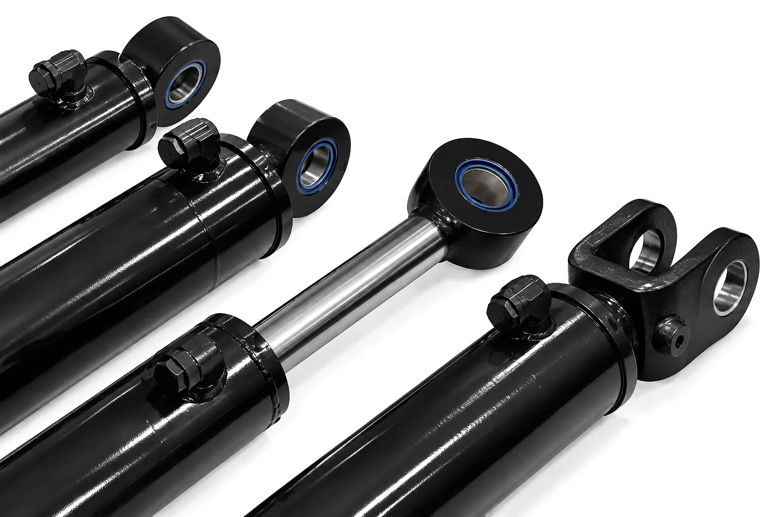
Boom Cylinder Technical & Performance Specification Table
| パラメータ | Standard Range | Heavy-Duty Range | Notes |
|---|---|---|---|
| 穴径 | 40 – 200 mm | 200 – 500 mm | Custom non-standard bores available on request |
| ストローク長 | 100 – 2,000 mm | Up to 6,000 mm | Telescopic cylinders available for very long strokes |
| 作動圧力 | Up to 250 bar | Up to 350 bar | Burst pressure tested at 2× working pressure |
| ロッドの直径 | 28 – 160 mm | 160 – 360 mm | Designed to Euler buckling limits per stroke |
| Max Extension Force | Up to 785 kN | Up to 6,872 kN | At 250 bar / 350 bar respectively |
| 樽の材質 | E355 seamless steel | 34CrMo4 alloy steel | Honed to Ra 0.2–0.4 µm |
| Rod Surface | Hard chrome 25 µm | 30 µm Ni-Cr / DLC optional | Salt spray tested to 200 h minimum |
| 動作温度 | -20℃~+80℃ | -40℃~+120℃ | Low-temp seals available for Arctic-grade operation |
| Seal Standard | PU/NBR composite | FKM Viton / PTFE | Hallite, Parker or equivalent OEM grade |
| 取り付けオプション | Pin eye, clevis, flange | Trunnion, spherical bearing | Custom mounting to CAD drawing |
Industrial Application Scenarios: Where Bore and Stroke Decisions Are Made
On a 20-tonne excavator working Birmingham ring-road improvements, the main boom cylinder typically carries a 140 mm bore and a 1,200 mm stroke. The bore produces 385 kN push force at 250 bar — enough to lift the dipper arm and bucket plus full-rated payload through a full dig cycle. The stroke defines the elevation sweep from ground-level dig to tip height over a haulage truck. Correct specification here prevents strain on the pilot circuit and keeps cycle times competitive. The カスタム油圧パワーユニット paired with these cylinders ensures pressure delivery stays consistent across multiple actuators simultaneously.
In Sheffield’s surviving special-steels sector, hydraulic cylinders on overhead transfer cranes and tilt tables face loads of 50 to 150 tonnes. Bore diameters of 250 to 400 mm are common, often with strokes under 800 mm because the geometry is constrained by the press-bay ceiling height. The critical parameter is not speed but controllability at very low extension rates — often 2 to 5 mm per second — to maintain even load distribution across multi-point lifting frames. Seal performance under slow-speed, high-pressure conditions is more demanding than high-speed cycling, as squeeze-film lubrication between seal and rod is minimal at very low traverse speeds.
Front loader boom cylinders on UK farm telehandlers and tractors operate in the 63 to 100 mm bore range with strokes from 600 to 900 mm, running at system pressures of 180 to 210 bar. The relatively modest bore keeps oil volumes manageable with the tractor’s open-centre hydraulic circuit, while the stroke provides adequate lift height to load grain trailers and clear yard walls. Resistance to contamination — from chaff, fertiliser dust, and moisture on farms in Lincolnshire, Yorkshire, and East Anglia — drives the choice of wiper seal material as much as the bore and stroke specification itself.
Cargo-handling cranes at ports including Liverpool, Southampton, and Tilbury use boom cylinders in the 180 to 320 mm bore range, often with nickel-chrome plated or stainless-steel rods to resist the salt-air corrosion that destroys standard hard-chrome in under 12 months. Stroke lengths here depend on the crane’s luffing geometry rather than any fixed standard. A key design consideration is the cushioning arrangement at end-of-stroke — particularly important in deck cranes where dynamic wave loading transmits impact forces into the cylinder at the moment of full extension.
Municipal waste compaction bodies operating across councils from Glasgow to Bristol rely on cylinders with 100 to 160 mm bores and relatively short strokes of 400 to 700 mm, but they cycle 800 to 1,200 times per working day. This extreme duty cycle makes seal wear resistance and chrome quality the dominant specification criteria. Bore and stroke alone do not tell the full story here — the cycle life target, typically 2 million cycles to first seal change, must inform material and surface treatment choices before any bore or stroke can be confirmed with a supplier.
High-reach demolition excavators used on urban regeneration projects in Manchester city centre, Leeds, and along London’s ongoing infrastructure corridors can carry boom cylinders with 160 to 200 mm bores on the primary arm, running at up to 320 bar. The operating environment is arguably the harshest in the UK industry — flying concrete debris, vibration, and repeated high-pressure shock spikes from the shear attachment impact loading. Stroke selection on these machines is dictated by the high-reach geometry and must be validated against Euler buckling calculations for the extended rod at maximum working pressure, a calculation Ever Power carries out as a standard deliverable for every custom order in this category.
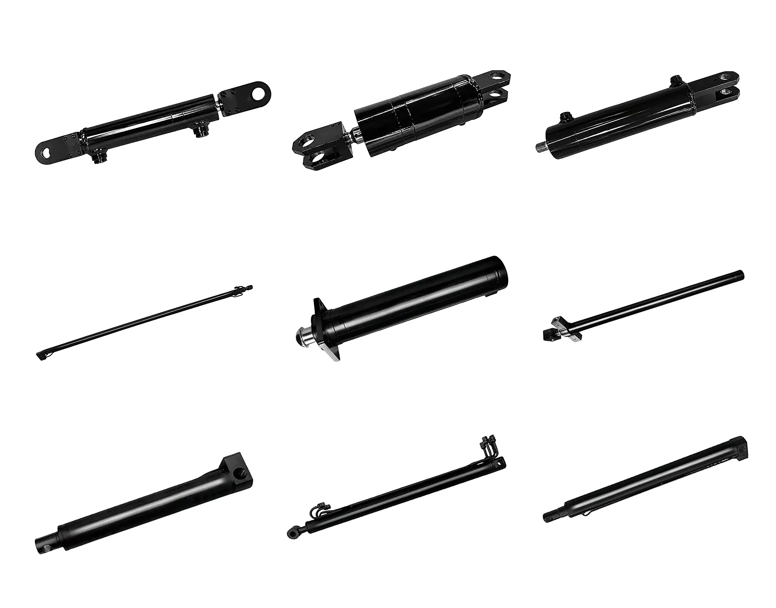
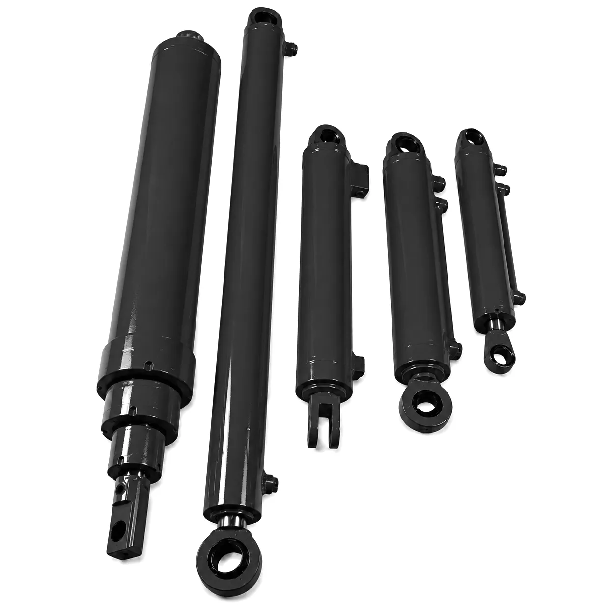
Customer Success Story: Sheffield Steel-Handling Gantry Cylinder Replacement
Rotherham Structural Steel Ltd operates a fabrication facility in the Don Valley, handling structural beams up to 18 metres in length and 12 tonnes per lift. Their gantry crane tilt arm runs on two matched boom hydraulic cylinders, 200 mm bore, 950 mm stroke, operating at 280 bar to tilt long beams onto roller conveyors for welding and surface treatment. The original OEM cylinders — sourced from a European supplier who had since discontinued the product line — developed internal bypass at the piston seal, resulting in uncontrolled drift of 8 mm per minute under full load. On a beam weighing 10 tonnes, that rate of drift was unacceptable for operator safety and work-positioning accuracy.
The maintenance engineering team contacted Ever Power with the original dimensional drawings. Because the bore and stroke were non-standard relative to catalogue sizes, they had struggled to find a replacement in the UK market without committing to a minimum order of twelve units from an alternative European supplier. Ever Power produced two matched replacement cylinders to the original bore and stroke with upgraded piston seals, new chrome rod surfaces, and internal cushioning added at both end-of-stroke positions. Delivery to Sheffield via Felixstowe took 21 working days. The gantry returned to service with zero-detectable drift under load and improved end-of-stroke damping that reduced steel frame vibration at the approach to full extension.
The project also identified that the original cylinder’s stroke had been specified 40 mm shorter than the gantry geometry actually required, causing the tilt arm to reach end-of-stroke impact on every cycle rather than stopping in the cushion zone. Ever Power’s engineering team reviewed the mounting geometry drawings and suggested a 40 mm stroke increase for the replacement units, eliminating end-stop impact fatigue that had been progressively damaging the rod-end clevis on both original cylinders over the previous four years of operation.
“Ever Power matched our non-standard 200 mm bore and 950 mm stroke without any issue. The replacement units arrived with full pressure test certificates and the bore finish was measurably better than what we’d had before. Drift under load has been completely eliminated.”
“The engineering team picked up the stroke undersize issue from our drawings — something we hadn’t connected to the end-stop damage. Suggesting a 40 mm stroke correction without being asked for it is exactly the kind of detail that saves serious money over the life of the machine.”
“We’d been quoted a minimum of twelve units from the original European supplier. Ever Power produced two matched units, shipped directly, with no minimum order constraint. For a facility our size, that supply flexibility is as important as the specification quality.”
Core Technical Advantages of Ever Power Boom Hydraulic Cylinders
FAQ — Boom Cylinder Bore and Stroke Questions from UK Engineers
How do I work out what bore size I need for my excavator’s boom hydraulic cylinder when I’m replacing a failed unit on a construction project in Birmingham?
The quickest route is to measure the internal barrel diameter of the failed cylinder with a bore gauge or digital caliper. If the cylinder is beyond disassembly, the bore can usually be cross-referenced from the OEM service manual using the machine model number. If neither is available, calculate the required force from the machine’s rated lift capacity, work backwards using F = P × (π/4 × D²) at your system pressure, and round up to the nearest standard bore. Contacting Ever Power with your machine make and model often produces a match from the team’s OEM cross-reference database.
What is the typical price or cost for a custom-bore boom hydraulic cylinder supplied to a UK engineering company, and how quickly can I get a quote from a manufacturer?
Custom boom cylinder pricing depends primarily on bore diameter, stroke length, working pressure rating, rod specification, and mounting type. A 100 mm bore, 1,000 mm stroke unit at 250 bar in standard steel configuration typically falls in the £280–£420 ex-works range for single-unit orders. Heavy-duty configurations at larger bores cost proportionally more. Ever Power provides formal quotations within 24–48 hours of receiving full dimensional requirements. Email [email protected] with your bore, stroke, pressure rating, mounting details, and required quantity for a return quote.
Which UK supplier can manufacture a non-standard boom cylinder bore and stroke combination without requiring a large minimum order quantity?
Ever Power accepts single-unit custom orders for non-standard bore and stroke combinations with no minimum order requirement. This is specifically relevant for replacement and prototype work where committing to batch quantities is not economically viable. The factory’s flexible CNC honing lines allow bore diameters outside the standard catalogue range to be produced efficiently at low quantities. UK procurement engineers dealing with legacy machine specifications from discontinued European OEM lines have successfully sourced single replacement units through Ever Power for this reason.
How does increasing the stroke length of a boom cylinder affect the rod diameter selection and buckling risk on heavy-duty lifting equipment in Sheffield’s steel industry?
Longer strokes increase the unsupported length of the piston rod when the cylinder is at or near full extension, which raises the risk of Euler column buckling under compressive load. For every increase in stroke, the rod diameter must be recalculated to keep the slenderness ratio within safe limits — typically the critical buckling load is specified at four times the rated working force for a fixed-free end condition. In Sheffield’s steel-handling applications, buckling calculations often drive rod diameters to 60–70% of bore diameter. Ever Power provides these calculations as standard on all long-stroke custom orders.
When should I consider a custom bore hydraulic cylinder instead of an off-the-shelf standard size for my UK agricultural machinery loader arm replacement?
Standard bore sizes (40, 50, 63, 80, 100, 125, 160, 200 mm) cover the vast majority of agricultural loader arm applications. A custom bore becomes necessary when the original machine was designed around an imperial bore size — such as 3.5 inch or 4 inch — that does not match any metric standard, or when the payload and pressure combination falls between two standard bore outputs. An easy first check: measure your original cylinder bore and compare it against the standard metric series. If it is off by more than 1.5 mm, it is almost certainly a custom or imperial size.
Where can a plant hire company in the UK find a reliable hydraulic cylinder supplier that can match OEM bore and stroke specifications with fast lead times for fleet maintenance?
Ever Power supplies directly to plant hire companies and fleet maintenance operations across the UK, with shipping via Felixstowe and Southampton to minimise transit time. Standard configurations ship within 15 working days; urgent replacement orders are assessed for expedited production on a case-by-case basis. The team maintains an OEM cross-reference database covering major excavator, crane, and handler brands. Contact [email protected] with the machine model, cylinder location, and any available dimensional data for a rapid response.
Have a bore and stroke specification question? Contact the Ever Power engineering team directly.
📧 [email protected] — Get a Quote
gzlによる編集
 Japanese
  English
  Italian
  Portuguese
  Dutch
Dutch  Swedish
  Danish
  Finnish
  Polish
  Hindi
Hindi  Kazakh
  Turkish
  Ukrainian
  Romanian
  Spanish
  German
  Russian
  Korean
  Vietnamese
  Thai
Thai  Indonesian
  Malay
Malay  French
  Greek
Greek