
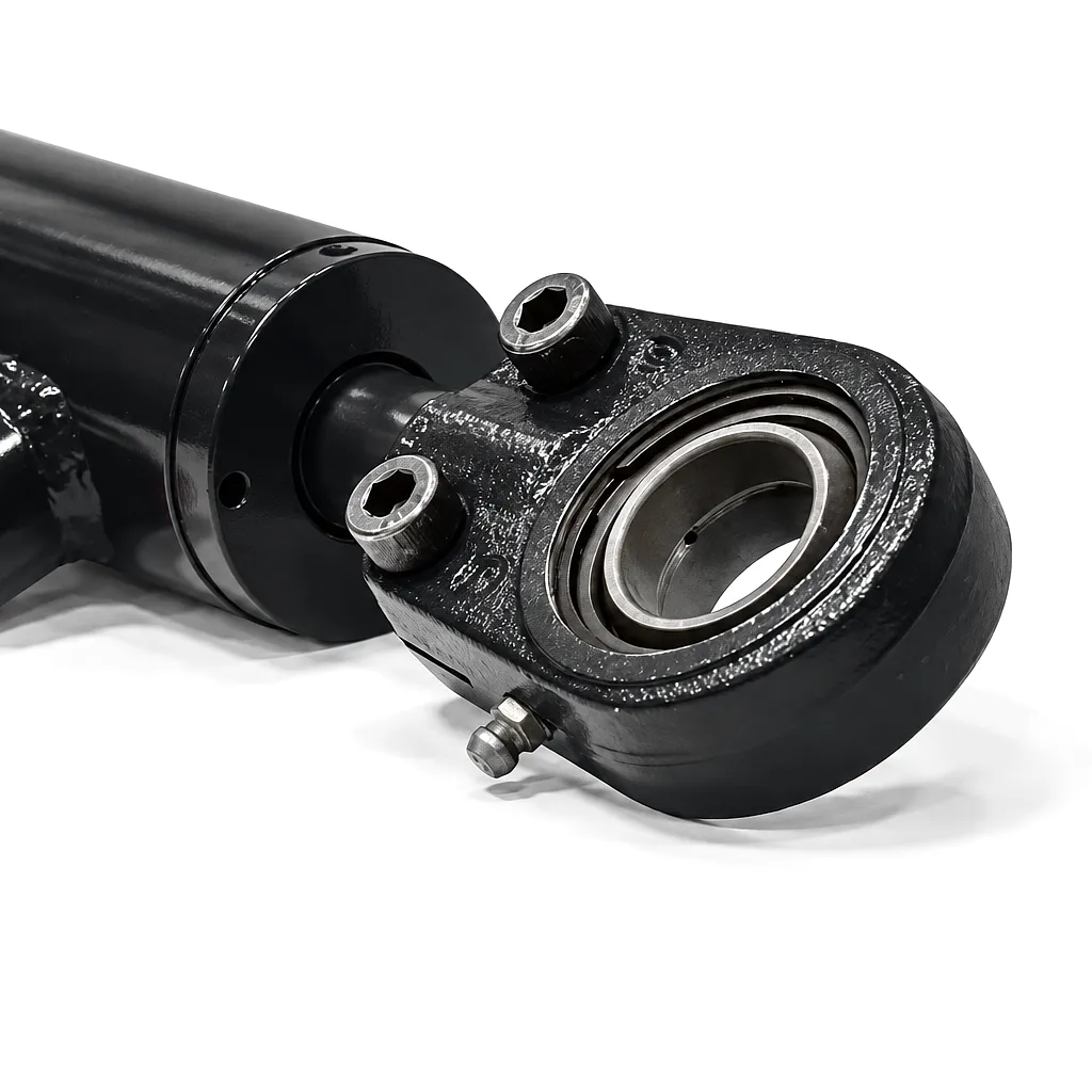
 Specifying the correct bore size for a hydraulic cylinder is one of those decisions that looks simple on the surface yet carries enormous consequence in real-world operation. Get it right and the machine delivers rated force reliably across its entire working life. Get it wrong and you are dealing with premature seal failures, underperformance under load, excessive heat generation, or — in the worst case — a cylinder that cannot safely sustain the pressure demands placed on it by the system. For UK manufacturers in sectors ranging from agricultural machinery assembly in Lincolnshire to heavy fabrication shops in Sheffield and Birmingham, bore sizing is a specification that deserves careful, data-driven attention.
This technical guide brings together standard bore dimension charts aligned to ISO 6020 and BS EN 3863 references, explains how bore diameter interacts with pressure rating and output force, and maps those parameters directly onto the application demands common across British industry. Whether you are sourcing for OEM production runs, plant maintenance, or bespoke fabrication projects, the dimensional data and selection principles here are designed to cut specification time and reduce the risk of costly mismatches.
What Hydraulic Cylinder Bore Size Actually Means — and Why It Matters
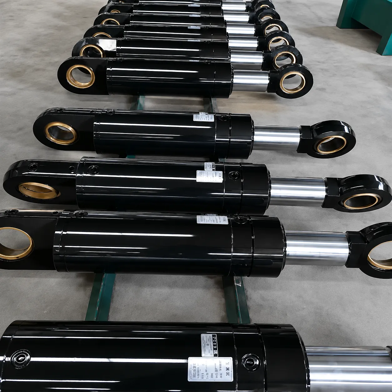 The bore of a hydraulic cylinder is simply the internal diameter of the barrel — the cavity through which the piston travels. This single measurement is the primary determinant of how much force the cylinder can generate. The relationship is governed by a straightforward formula: Force (F) equals Pressure (P) multiplied by the effective piston area (A), where A = pi * (D/2)^2 for the cap-end stroke and accounts for the rod cross-section on the rod-end return stroke.
What this means in practical terms is that even modest changes in bore diameter translate into significant shifts in output force. Moving from a 63 mm bore to an 80 mm bore at the same system pressure of 250 bar does not produce a proportional 27% increase in force — because the area scales with the square of the radius, the actual force gain is closer to 60%. This non-linear relationship is exactly why engineers must resist the temptation to simply “go one size up” without recalculating the full force balance of the system, including counterloads, friction margins, and safety factors required by BS PD 5500 and related British standards for pressure equipment.
The hydraulic cylinder bore size also interacts directly with seal geometry, barrel wall thickness, and the rod diameter ratio — all of which are standardised within defined families so that off-the-shelf seals, end caps, and mounting accessories remain interchangeable across compatible units.
Standard Bore Size Chart — ISO and Industry Reference Dimensions
The table below covers the most widely specified bore diameters for both industrial hydraulic cylinders and agricultural hydraulic cylinders used across the UK market. All force values are calculated at a reference system pressure of 250 bar (25 MPa), which is the most common rated pressure for medium-duty tie-rod and welded cylinders in British OEM and plant applications.
| Bore Dia. (mm) | Bore Dia. (in) | Piston Area (cm²) | Extend Force @ 250 bar (kN) | Typical Rod Dia. (mm) | Typical Application |
|---|---|---|---|---|---|
| 32 | 1.26 | 8.04 | 20.1 | 22 | Small valves, door actuators, light tooling |
| 40 | 1.57 | 12.57 | 31.4 | 28 | Injection moulding clamping, conveyor gates |
| 50 | 1.97 | 19.63 | 49.1 | 35 | Agricultural seeders, small tractor linkages |
| 63 | 2.48 | 31.17 | 77.9 | 45 | Round balers, plough frames, lift systems |
| 80 | 3.15 | 50.27 | 125.7 | 56 | Excavator booms, tipping trailers, presses |
| 100 | 3.94 | 78.54 | 196.4 | 70 | Crane outriggers, tipper bodies, forestry equipment |
| 125 | 4.92 | 122.72 | 306.8 | 90 | Hydraulic presses, offshore deck equipment |
| 160 | 6.30 | 201.06 | 502.7 | 110 | Steel mill rolling equipment, mining machinery |
| 200 | 7.87 | 314.16 | 785.4 | 140 | Large presses, shipbuilding, bridge lifting |
| 250 | 9.84 | 490.87 | 1227.2 | 180 | Dam gates, heavy industrial presses, tunnelling |
Note: Force figures are theoretical at 250 bar without deducting friction and seal drag losses. Practical efficiency factor of 0.92–0.96 is typically applied for specification purposes. Rod-end retract force must be calculated separately using annular area.
How a Hydraulic Cylinder Converts Pressure Into Linear Force
Pressurised fluid enters the cap end of the barrel, acting across the full bore area of the piston face. This generates the maximum available thrust force. As the piston advances, fluid on the rod side exits through the rod-end port, returning to the hydraulic reservoir or regenerating into the system. The relationship F = P * A means that a 100 mm bore cylinder at 200 bar develops approximately 157 kN of extend force — enough to lift over 16 tonnes against gravity.
On the return stroke, fluid enters the rod-end port and acts against the annular area of the piston — the bore area minus the rod cross-sectional area. This smaller effective area means retract force is always lower than extend force at the same system pressure. Engineers must verify that retract force is sufficient for the return-load requirements of the application, particularly in vertical mounting arrangements where the cylinder must overcome gravity as well as counterloads such as spring returns or attached tooling weight.
The barrel wall must be thick enough to contain working pressure safely with an adequate factor of safety — typically a minimum of 2.5:1 for industrial duty across standard UK plant specifications. Wall thickness is calculated from bore diameter, material yield strength, and the maximum system pressure including pressure spikes from directional valve switching. For high-bore cylinders operating above 350 bar, honed seamless steel tube is mandated as the barrel material rather than drawn-over-mandrel tube, which may carry residual stress concentrations near the weld seam areas.
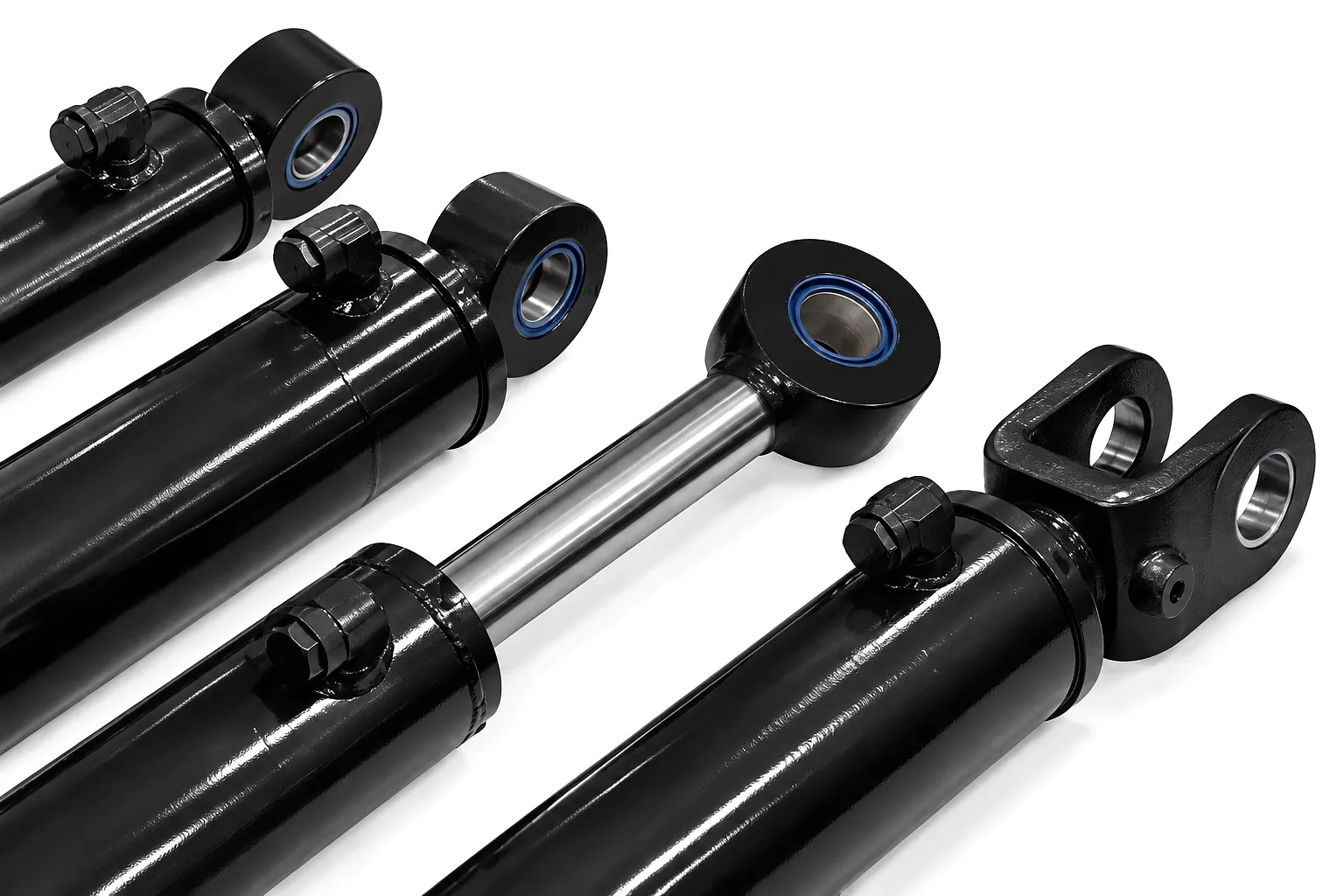
Core Materials in Hydraulic Cylinder Manufacture
The cylinder barrel is produced from seamless cold-drawn tube in St52 or the EN equivalent E355 grade. After rough machining, the bore is honed to Ra 0.2–0.4 micrometers surface finish. This mirror-like honing quality is not cosmetic — it is the foundation for seal longevity. A poorly finished bore accelerates the abrasive wear of polyurethane lip seals and can halve seal service life in high-cycle agricultural applications. UK buyers sourcing from quality-certified manufacturers should always request honing records as part of their goods inspection documentation.
Piston rods are manufactured from CK45 carbon steel bar, precision-ground, and hard chrome-plated to a minimum depth of 20–25 microns with a surface hardness exceeding HV 850. The chrome layer provides corrosion protection across the range of British field environments — from the salt-laden air of coastal agricultural operations in Norfolk and Suffolk to the mineral-rich mud exposure typical of construction work around the Scottish Highlands and Northern England. For highly aggressive environments such as offshore platforms or intertidal engineering, stainless steel 316L rods with induction hardening or nitride treatment offer a step-change in corrosion resistance without sacrificing surface hardness.
Seal selection is intimately linked to bore size because bore diameter governs the radial compression force of the seal lip and the volumetric displacement per cycle. Standard-duty seals in polyurethane (PU) operate reliably from -30 degrees C to +100 degrees C and are chemically compatible with mineral hydraulic oil, the most common fluid type in UK plant hydraulics. For fire-resistant fluid applications — mandated in specific mining and steel-processing environments under UK regulations — the seal compound shifts to PTFE-based or EPDM materials that can handle phosphate ester or water-glycol fluids without swelling or degradation.
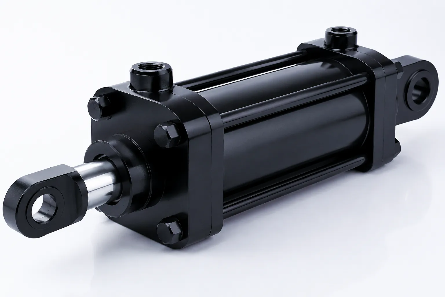
Head and cap end covers are machined from ductile iron (GJS-400 or GJS-500 grade) for standard-duty cylinders or forged alloy steel for high-pressure and high-cycle-rate duty. The thread engagement between barrel and end cap is a critical stress concentration zone — precision thread grinding and minimum 1.5D engagement length are mandatory for cylinders operating above 200 bar. Tie-rod designs distribute load through four or more hardened steel rods and are easily disassembled for field seal replacement, which makes them the preferred configuration for UK agricultural operators who require rapid in-season servicing without specialist tooling.
Key Performance Advantages of Correctly Sized Hydraulic Cylinders
Bore sizing matched to load requirements eliminates energy waste from oversized cylinders running at partial pressure and prevents force shortfalls from undersized units. This translates directly into lower hydraulic pump demand, reduced heat generation, and longer fluid service intervals.
When bore diameter is correctly specified with an appropriate rod diameter ratio, the seal contact pressure remains within the optimal operating band. Excessive contact stress from oversized rods in undersized bores is a leading cause of premature seal extrusion, particularly in tie-rod cylinders running high-cycle agricultural applications through harvest season.
Sticking to standard ISO bore sizes means seals, piston rings, wear bands, and end fittings are available from multiple suppliers and stocked by hydraulic trade distributors across the UK — including major distribution hubs in Birmingham, Manchester, and Bristol. This avoids the costly lead times associated with non-standard bore cylinders when urgent field repairs are needed during peak operating periods.
Bore area directly determines piston speed for a given flow rate (v = Q/A). Specifying the correct bore ensures that flow control valves and proportional directional valves operate within their rated flow bands, maintaining the smooth velocity profiles demanded in precision industrial presses, automated assembly lines, and hydraulic jigs common across UK engineering subcontractors in the West Midlands and Yorkshire manufacturing belts.
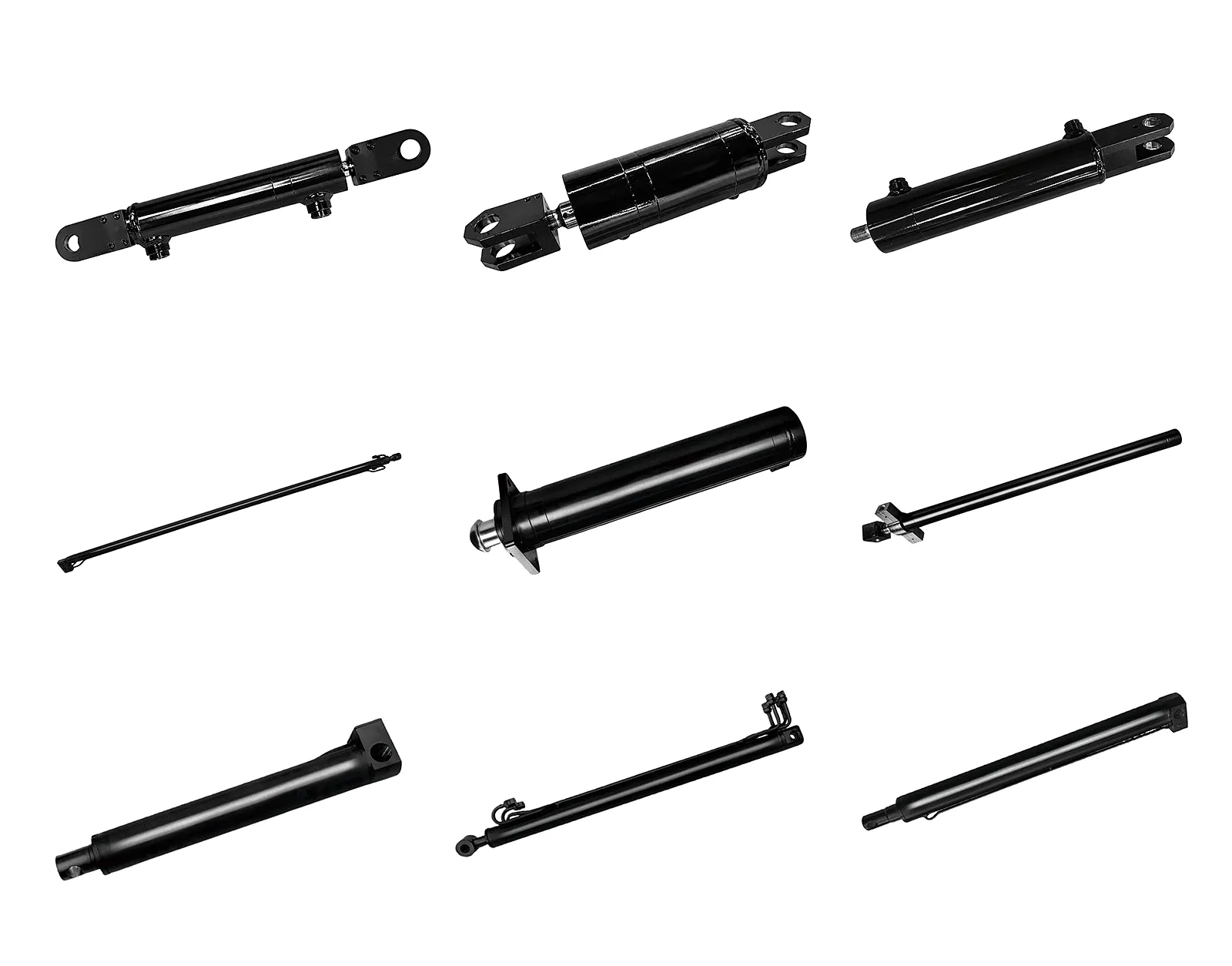
Industrial and Agricultural Application Scenarios Across the UK
The appropriate bore size varies enormously across application sectors. Understanding which bore range has become standard in each sector helps engineers start from a validated reference point and adapt from there rather than starting the sizing calculation from scratch.
Hydraulic Cylinder Technical Performance Specification Table
The following comprehensive specification table covers typical parameter ranges for tie-rod and welded body hydraulic cylinders supplied by Ever Power for industrial and agricultural buyers in the UK. All values represent standard production ranges; non-standard bore and stroke combinations are available through custom order.
| Parameter | Tie-Rod Series | Welded Body Series | Telescopic Series | Eenheid |
|---|---|---|---|---|
| Standard Bore Range | 32 – 160 | 50 – 320 | 80 – 250 (outer) | mm |
| Maximale slag | Up to 3,000 | Up to 8,000 | Up to 5,000 (extended) | mm |
| Rated Pressure | 160 – 250 | 250 – 400 | 160 – 250 | bar |
| Proof Test Pressure | 1.5x rated | 1.5x rated | 1.5x rated | — |
| Vatmateriaal | E355 honed | St52 / E355 honed | St52 honed | — |
| Bore Surface Finish (Ra) | 0,2 – 0,4 | 0,2 – 0,4 | 0.2 – 0.5 | micrometers |
| Rod Material | CK45 chrome-plated | CK45 chrome / SS316 | CK45 chrome-plated | — |
| Diepte van de chroomlaag | 20 – 25 | 20 – 30 | 20 – 25 | microns |
| Standard Seal Type | PU / NBR | PU / PTFE | PU / NBR | — |
| Bedrijfstemperatuur | -30 to +100 | -30 to +150 | -20 to +80 | degrees C |
| Mounting Options | Flange / Clevis / Foot | Flange / Clevis / Trunnion | Base / Collar / Pin | — |
| Cushioning | Fixed / Adjustable | Fixed / Adjustable / None | None / Fixed | — |
Ever Power: Precision Manufacturing and Unlimited Customisation
Ever Power operates one of the most comprehensively equipped hydraulic cylinder production facilities in China, with a dedicated product line serving UK and European B2B buyers across industrial and agricultural sectors. Our manufacturing capability stretches across every bore size from 32 mm to 500 mm with custom stroke lengths accepted from single-unit prototype to full OEM production runs of several thousand units per month.
Where standard hydraulische cilinders in catalogue bore sizes meet 80% of application needs, the remaining 20% — the hardest, most demanding, and most application-specific requirements — is where Ever Power’s engineering team genuinely differentiates. Non-standard bore combinations, custom port positions, integrated position sensor housings for LVDT or magnetostrictive transducers, bi-directional cushioning valve blocks, and custom metallurgy for corrosive or cryogenic environments are all within our standard customisation scope. UK buyers benefit from a dedicated technical liaison service that bridges the specification gap between the application engineer’s requirement and the production drawing, with documented revision rounds and formal drawing approval before any steel is cut.
Our supply chain reliability is underpinned by dedicated raw material inventory covering 12 bore sizes in three barrel wall thicknesses, a comprehensive seal stock holding covering all standard bore variants in both PU and PTFE compounds, and a production scheduling system that has maintained on-time delivery rates above 97% to UK customers over the past three years — even through the logistical disruptions of the post-Brexit regulatory adjustment period.
Send us your bore size, stroke, pressure rating, mounting configuration, and quantity requirements. Our engineering team responds within 24 hours with a costed proposal and full technical datasheet.
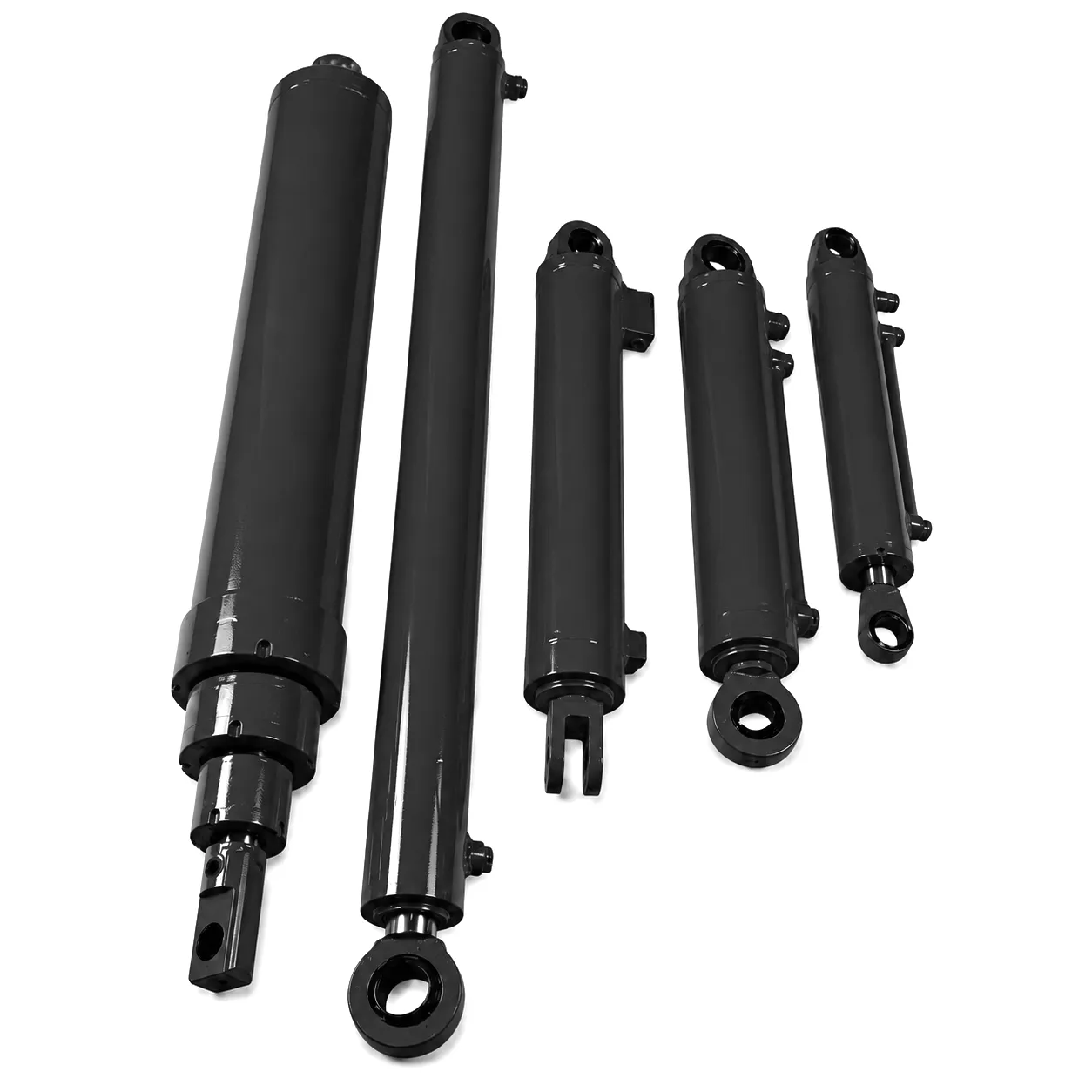
Birmingham Press Line Upgrade: From Chronic Downtime to 94% Uptime with Custom 125 mm Bore Cylinders
West Midlands Heavy Engineering — Metal Stamping and Pressing Sector
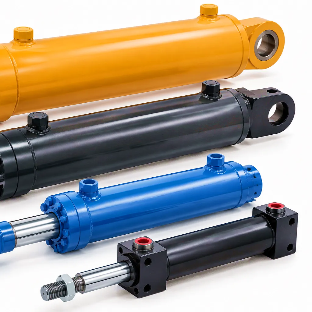 A mid-sized precision presswork manufacturer based in Birmingham’s Aston industrial corridor had been struggling for two years with repeated hydraulic cylinder failures on their four-press stamping line. The existing supplier’s 125 mm bore tie-rod cylinders were failing seal kits at an average interval of just 11 weeks — far short of the 12-month target — and each unplanned seal replacement was costing the business approximately £3,800 in lost production time per incident, in addition to parts and labour.
The root cause, identified by Ever Power’s technical team during a site visit coordinated through their UK logistics partner, was a combination of an undersized rod diameter for the bore (giving excessive seal extrusion risk under the 280 bar peak pressure spikes generated by the press control valve switching events) and a standard PU seal that was degrading in the synthetic ester press fluid the customer had switched to for fire resistance compliance under their site insurance requirements.
Ever Power proposed a direct replacement cylinder maintaining the 125 mm bore and existing stroke but upgrading the rod from 90 mm to 100 mm diameter, switching the seal compound to a PTFE-based set rated for synthetic ester fluids, and adding adjustable end-cushioning on the extend stroke to damp the pressure spike at end of stroke. The redesigned cylinder was prototyped, tested to 1.5x rated pressure, and eight production units were delivered to Birmingham within nine weeks of order placement.
Eighteen months after installation across all four press stations, not a single seal failure has been recorded. The line uptime figure has risen from 81% to 94%, and the annual maintenance budget for that press line has reduced by 34%. The customer has since placed a follow-on order for six additional cylinders to equip a new press cell being commissioned at their sister facility in Coventry.
“The technical input from Ever Power’s team before the order was placed was the key difference. They didn’t just sell us a cylinder — they identified the actual failure mechanism and redesigned around it. Eighteen months without a seal failure speaks for itself. We now specify Ever Power by name on all hydraulic cylinder requisitions.”
“Lead time was nine weeks for a custom-spec cylinder — better than anything comparable from European suppliers at twice the price. The bore dimensional tolerance on the delivered units was within 0.02 mm of the agreed drawing, and the honing finish on the barrel was genuinely impressive. These are production-quality cylinders, not catalogue filler.”
“We source a mixed range of bore sizes from 63 mm to 160 mm through Ever Power for our agricultural machinery rebuild operation. The consistency of dimensional accuracy across bore sizes is what I value most — the same fitting tolerance regardless of whether it’s a small tractor linkage cylinder or a large forager drum drive actuator. Service and documentation have always been straightforward for our import paperwork.”
Practical Bore Selection — A Working Checklist for Specification Engineers
Identify the maximum load the cylinder must move or hold, including all counterloads, friction estimates, and a safety factor of at least 1.25 for dynamic applications. This is your target extend force (F) in kilonewtons or tonnes-force.
Identify the rated pressure of the existing or planned hydraulic circuit. Common values are 160, 200, 250, 315, and 350 bar. Higher pressure allows smaller bore for the same force, but demands greater care in hose, valve, and fitting specification.
Use D = 2 * sqrt(F / (pi * P)) to find the minimum bore diameter. Then round up to the nearest standard ISO bore size from the chart above. Never round down — always round up to maintain the force margin.
Calculate the annular area from chosen bore and rod diameter, then calculate retract force at system pressure. Verify piston speed (extend and retract) from available circuit flow rate. Adjust rod diameter or bore if the velocity falls outside control valve rated range.
For strokes exceeding 10x the rod diameter, verify Euler buckling resistance using the mounting category (free-fixed, pin-pin, etc.) and load. Long, lightly loaded applications may require a larger rod diameter than the bore-to-rod ratio would normally suggest, to satisfy column strength requirements.
Veelgestelde vragen
Ready to Specify Your Hydraulic Cylinder?
Whether you need a standard bore tie-rod cylinder for agricultural equipment or a fully bespoke welded-body design for a demanding industrial press application, Ever Power’s engineering team is ready to assist. Send your specification to receive a detailed technical quotation.
 Dutch
Dutch  English
  Italian
  Portuguese
  Swedish
  Danish
  Finnish
  Polish
  Hindi
Hindi  Kazakh
  Turkish
  Ukrainian
  Romanian
  Spanish
  German
  Russian
  Korean
  Japanese
  Vietnamese
  Thai
Thai  Indonesian
  Malay
Malay  French
  Greek
Greek