
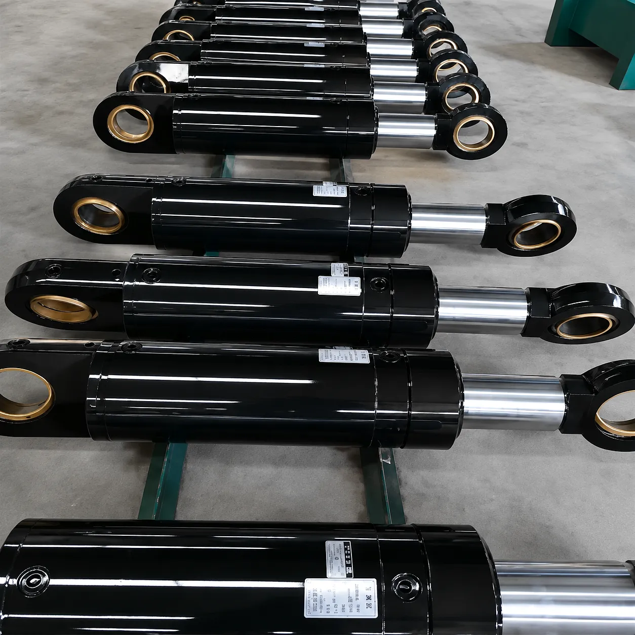
 Every time a JCB excavator lifts a load on a Sheffield construction site, or a crane boom swings materials across a Tyneside shipyard, there is a single mechanical component doing the heavy lifting behind the scenes — the boom cylinder. This hydraulic actuator converts fluid pressure into controlled linear force, and understanding how that conversion happens, step by step, is the foundation of smarter equipment specification, better maintenance scheduling, and more confident procurement decisions. In this guide we work through the full hydraulic circuit from pump to piston, explain the role of each component, and connect the physics to real-world operating conditions you will encounter across the UK’s demanding industrial environment.
Step 1 — Generating Pressure: From Reservoir to Pump
The hydraulic circuit of a boom cylinder system begins at the reservoir — a sealed tank containing hydraulic oil, typically mineral-based ISO VG 46 or VG 68 grade, maintained at controlled temperature. A variable-displacement axial-piston pump, driven by the machine’s diesel engine or electric motor, draws fluid from this reservoir and delivers it at working pressure. On modern excavators and crane systems used across UK construction sites, system pressures routinely sit between 250 and 350 bar during peak demand. The pump does not create pressure in isolation; pressure is a reaction force — it builds because the downstream circuit resists flow. At idle, with no actuator commanded, a pressure-relief valve caps system pressure and returns flow to tank at near-zero differential, protecting hoses and seals from overpressure damage.
Flow conditioning happens before the fluid reaches any control valve. Inline filters rated at 10 microns or finer strip particulate contamination that would score cylinder bores and damage valve spools. A hydraulic cooler — often mounted ahead of the radiator on wheeled machines — keeps oil temperature below 80°C, beyond which viscosity drops sharply and film strength deteriorates. On heavy plant working in the warm summers of the South West or the cold winters of the Scottish Highlands, thermal management is engineered differently, adjusting bypass valve settings and cooler sizing to match ambient conditions. This foundational conditioning stage is what separates a boom cylinder that lasts 12,000 service hours from one that fails at 3,000 — clean, cool oil is the single biggest factor in longevity, ahead of even cylinder wall hardness.
Step 2 — Directing the Flow: The Control Valve Stack
Pressurised fluid arrives at the directional control valve — the nerve centre of the hydraulic boom circuit. In most excavators and telehandlers, this is a proportional electro-hydraulic spool valve, operated either by pilot pressure from a joystick command or by direct electrical signal from the machine’s control module. When the operator pushes the boom-up command, the spool shifts, opening a metered passage between the pump pressure line and the cap-end port of the boom cylinder. Simultaneously, it opens the return path from the rod-end port back to tank. The geometry of the spool land edges determines how flow ramps up: aggressive land angles give rapid response; gentle tapers give smooth, proportional movement — a distinction that matters enormously on lift-and-place operations at a Birmingham automotive body shop where millimetre-accurate positioning is required every cycle.
Load-holding and counterbalance valves sit between the control valve and the cylinder ports. These are safety-critical devices: if a hose bursts between the control valve and the cylinder while the boom is raised with a load, a counterbalance valve prevents the boom from dropping uncontrolled. It only permits oil out of the cap-end when pilot pressure from the extending rod-end line confirms deliberate operator input. This arrangement is mandatory under the LOLER 1998 (Lifting Operations and Lifting Equipment Regulations) requirements that govern crane and lifting plant operation throughout England, Wales, Scotland, and Northern Ireland. For plant operators working near the public — on high-street construction projects in Edinburgh’s New Town or road schemes on the M60 corridor — these valves are not optional extras; they are legal requirements.
Step 3 — Inside the Cylinder: Pascal’s Law in Action
The Barrel and Piston
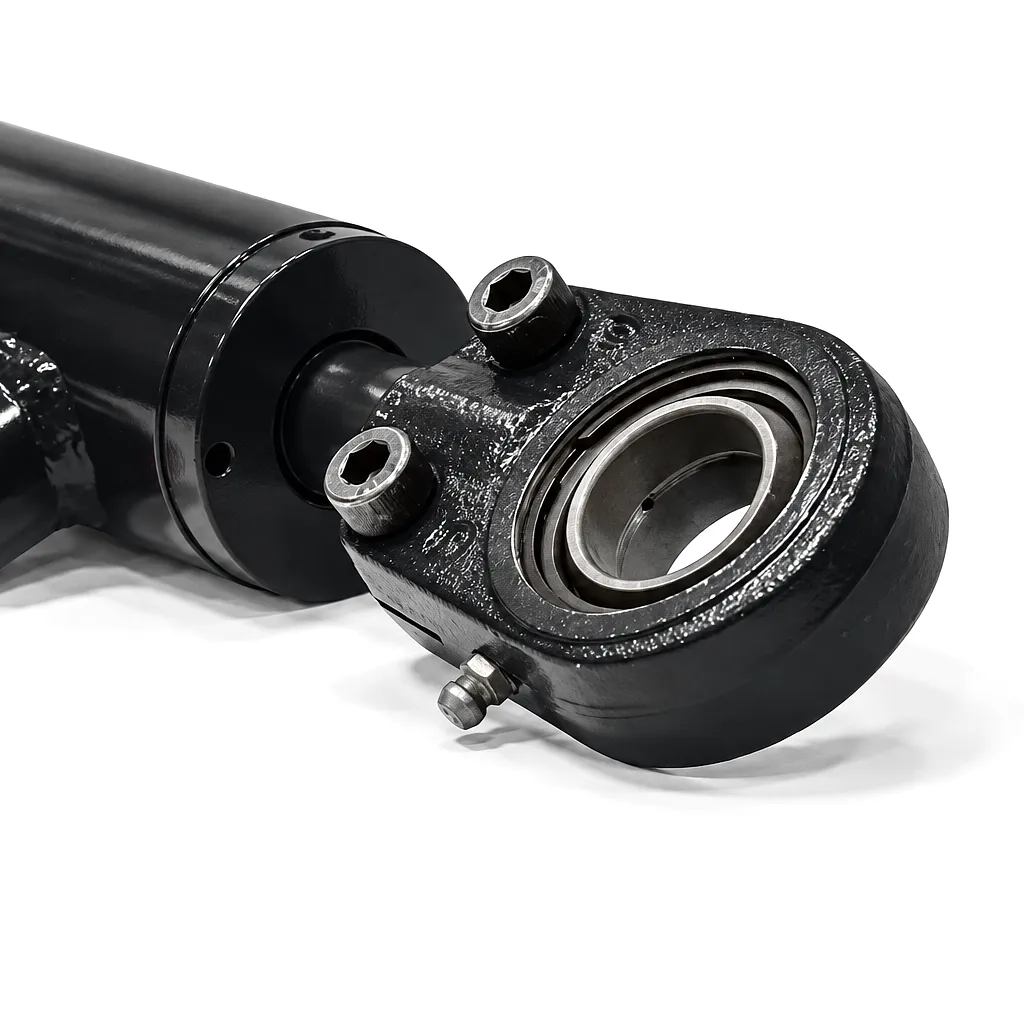
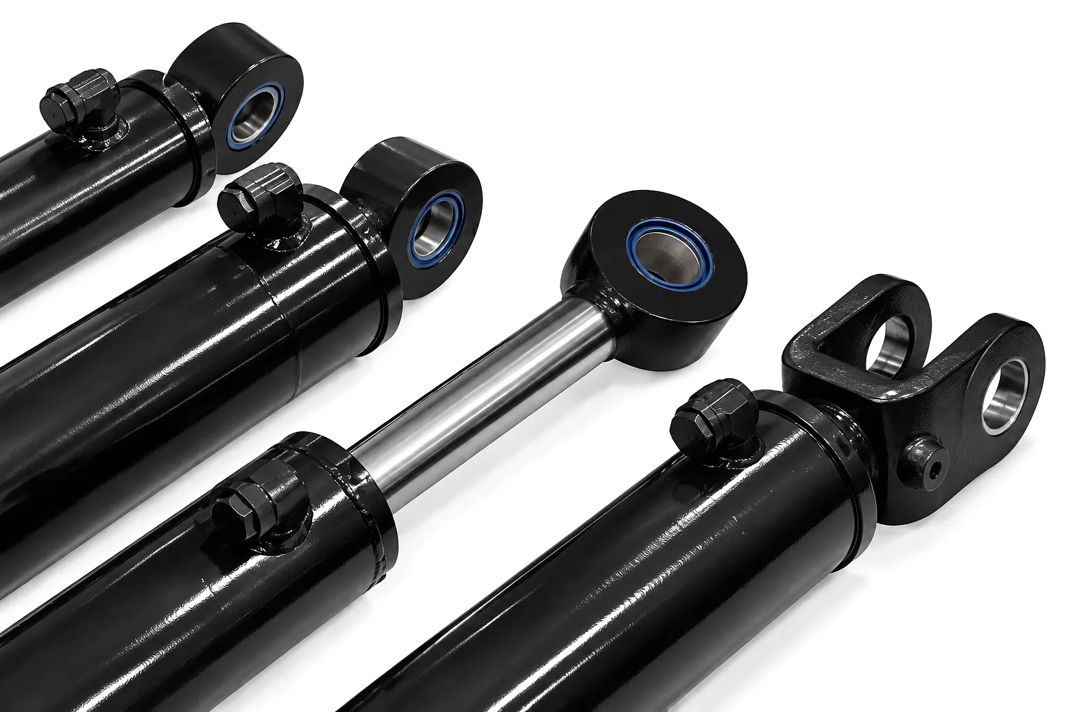
Inside the cylinder barrel, the hydraulic oil enters the cap-end chamber and acts on the full face area of the piston. According to Pascal’s law, pressure applied to an enclosed fluid transmits equally in all directions and acts on every unit of area equally. The force produced at the piston face equals the system pressure multiplied by the piston’s cross-sectional area. For a cylinder with a 120 mm bore operating at 280 bar, the theoretical extension force calculates to approximately 317 kN — enough to lift a heavily loaded trailer or push a mast section into position on a North Sea platform construction project. The piston seal package, typically a combination of wear rings, a stepped-cut primary seal, and an anti-extrusion backup ring, maintains the pressure differential between cap-end and rod-end without friction-induced stick-slip that would cause jerky boom movement.
The Piston Rod
The piston rod connects the internal piston to the external load attachment point. For boom cylinders, rod diameters are deliberately oversized relative to the force they must transmit in pure tension — because in practice the rod carries combined axial and bending loads as the boom angle changes. A 90 mm rod with a yield strength of 900 N/mm² (typical for S960QL steel used in heavy-duty boom cylinders) has a slenderness ratio that must be verified against Euler buckling criteria at full extension. The rod surface finish, usually hard chrome plating to a roughness of Ra 0.2 µm, is what the rod seal bears against. Damage to this surface — from stone strike on a forest-floor groundworks site in Wales, or corrosion from salt air on a coastal project in Dover — is the most common cause of rod seal failure and subsequent oil weeping. Protective rod sleeves or stainless-steel rod overlays are increasingly specified for demanding outdoor environments.
The Gland and Sealing System
The gland is the end cap through which the piston rod passes. It houses the rod seal pack — typically comprising a U-cup primary seal, a buffer seal to absorb pressure spikes, a rod guide bush to prevent metal-to-metal contact during lateral loading, a wiper seal to exclude contamination on the return stroke, and a dust seal for outdoor applications. Each element in this stack has a specific function, and omitting any one of them is a false economy that leads to premature contamination of the hydraulic system. The gland is threaded or flanged to the barrel and must remain concentric to the rod within tight tolerances: misalignment beyond 0.05 mm will cause uneven seal wear on one side, a failure mode that shows up as a slow, one-sided leak — often misdiagnosed as seal degradation when the real cause is a bent mounting trunnion or worn pin bush.
Core Materials Engineering: What the Cylinder Is Made From
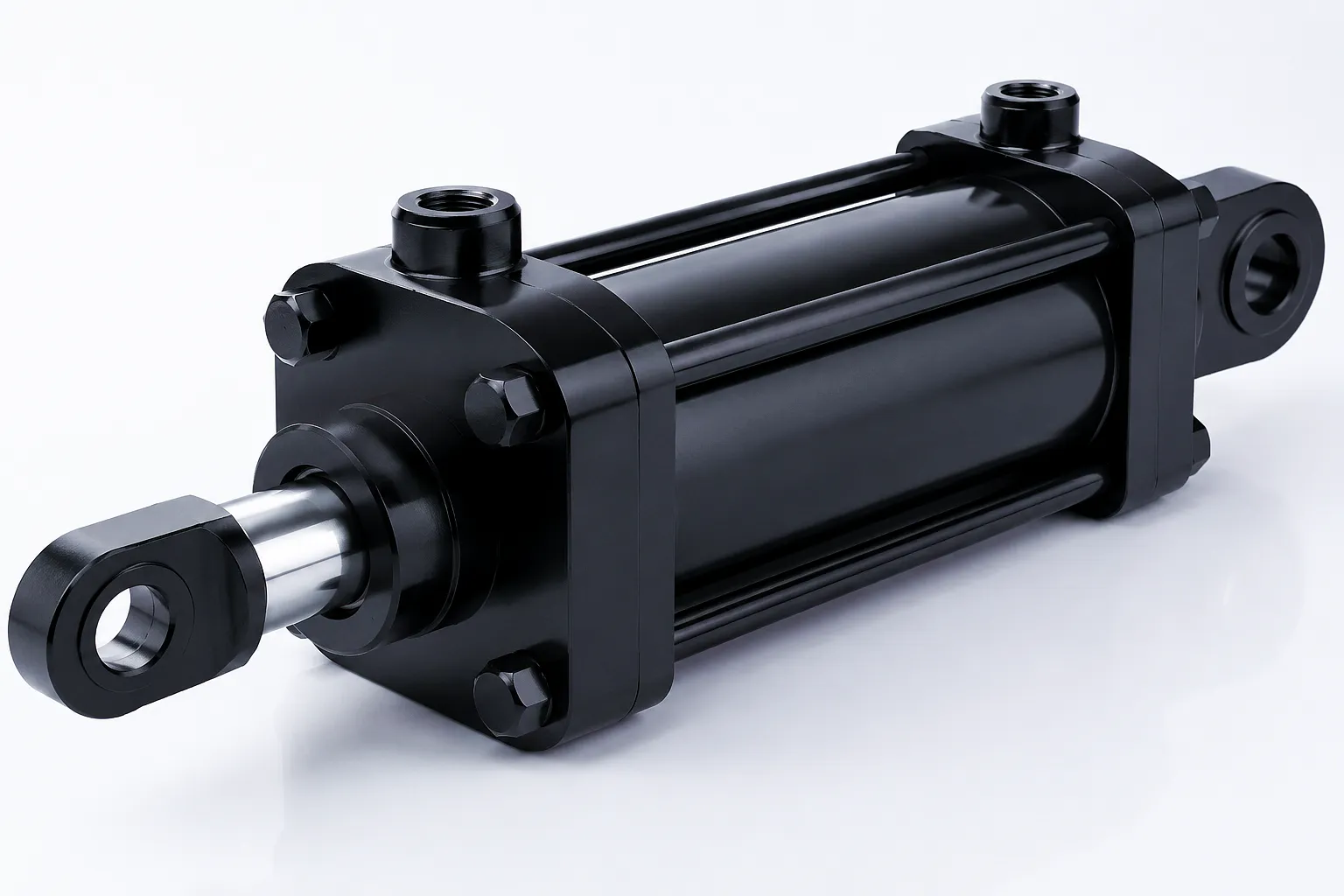 Material selection in boom cylinder manufacturing is not a commodity decision. Every alloy, surface treatment, and seal compound is chosen to survive a specific combination of pressure cycling, temperature swing, contamination risk, and mechanical shock. The wrong material choice in any single component can cascade into complete circuit contamination — a costly lesson that UK plant hire companies and offshore equipment managers have learned through experience on some of the country’s toughest job sites.
Barrel: Cold-Drawn Seamless Steel
The cylinder barrel is machined from cold-drawn seamless (CDS) steel tube, typically E470 or ST52 grade. Cold-drawing aligns the grain structure circumferentially, dramatically improving resistance to radial hoop stress under internal pressure. The bore is then precision honed to a surface finish of Ra 0.4 µm or better, which minimises piston seal friction and maximises seal service life. Skimping on bore finish quality — common in low-cost imports — increases friction, heat, and seal wear simultaneously.
Piston Rod: Induction-Hardened Alloy Steel
Rod material is typically 42CrMo4 (chromium-molybdenum alloy steel), quenched and tempered to a tensile strength of 900–1100 N/mm². The surface is induction-hardened to 54–62 HRC at the chrome layer interface, giving a hard, wear-resistant skin over a tough, ductile core. Hard chrome plating — typically 0.02–0.08 mm thickness — then provides the corrosion-resistant, low-friction bearing surface for the rod seal. For aggressive marine and offshore applications, nickel-PTFE composite coatings or HVOF (high-velocity oxygen fuel) tungsten carbide coatings are specified in place of conventional chrome.
Seals: Polyurethane and PTFE Compounds
Primary piston and rod seals are polyurethane (PU) in standard configurations — PU offers outstanding abrasion resistance, good chemical compatibility with mineral oil, and a working temperature range of -30°C to +110°C. Anti-extrusion rings are PTFE-bronze composite. Wiper seals are NBR (nitrile butadiene rubber) for standard temperatures, or FKM (Viton) where hydraulic fluid alternatives such as biodegradable ester fluids or fire-resistant phosphate esters are in use — increasingly common on UK rail and underground infrastructure projects under HSE fluid fire-resistance guidelines.
End Caps and Glands: Ductile Iron or Steel Forgings
Front glands and rear end caps in heavy boom cylinders are machined from either grade EN-GJS-400 ductile iron castings or steel forgings (S355 or 42CrMo4), depending on pressure rating and shock loading. Ductile iron provides excellent machinability and vibration damping — useful on rock-breaking or demolition machines common in Sheffield and other former heavy-industry cities undergoing urban regeneration. Forged steel glands are specified for cylinders rated above 350 bar or where section weights must be minimised, as in mobile elevated work platforms and aerial platforms used across UK building maintenance contracts.
Boom Cylinder Technical and Performance Parameter Table
The table below covers the principal design parameters and performance ranges across the Ever Power boom cylinder product range. All values reflect factory standard configurations; custom specifications are available on enquiry and are common for OEM and retrofit programmes.
Product Advantages: Why Engineered Boom Cylinders Outperform
High Pressure Density
Boom cylinders designed for 350+ bar operation deliver exceptional force-to-size ratios, reducing machine weight while increasing capability. Compact high-pressure designs allow OEMs to achieve CE-compliant lifts with shorter boom arms — a real advantage in restricted urban job sites across London and Manchester where outreach must be minimised.
Збільшений термін служби ущільнення
Multi-element seal stacks with buffer seals and anti-extrusion rings routinely deliver 8,000–12,000 operating hours before replacement is required, compared to 2,000–4,000 hours typical of single-element budget designs. For UK plant hire fleets running at 2,000+ hours per year, this extends overhaul intervals from twice-yearly to every 4–6 years, dramatically reducing workshop costs and machine downtime.
Adjustable End Cushioning
Built-in adjustable cushioning at both end positions decelerates the piston before it reaches the end cap, eliminating the hydraulic hammer that would otherwise fatigue mounting welds and fracture boom pin bushes. On recycling machinery and scrap-processing equipment operating in Sheffield’s materials-recovery sector, where cycles run at up to 40 strokes per minute, this feature alone can double structural component life.
Integrated Position Sensing
Magnetostrictive linear position transducers can be factory-integrated into the cylinder, eliminating external sensor mounting brackets and exposed cabling. Resolution of 0.1 mm and linearity of ±0.05% of full stroke enables closed-loop boom control, automated work-cycle programming, and condition-based maintenance trigger points — capabilities increasingly demanded by UK telehandler operators transitioning to telematics-enabled fleet management systems.
Corrosion Protection Systems
External surfaces are protected by a two-pack epoxy primer plus polyurethane topcoat system to ISO 12944 Category C4 or C5-M for offshore and coastal environments. The piston rod chrome plating is micro-crack-free chrome applied by controlled bath chemistry. For wind farm maintenance equipment operating along the UK’s North Sea coastline from Hull to Aberdeen, ever power applies additional zinc-rich primer layers and stainless-steel port fittings as standard.
LOLER and CE Compliance by Design
Every boom cylinder in the Ever Power range is designed with counterbalance valve ports, proof-pressure test documentation, and load-cell traceability to support LOLER examination and CE marking processes. Certificates of conformity, material mill certificates, and independent test reports are supplied as standard with each shipment, supporting the documentation requirements of UK contractor procurement teams and plant inspection bodies such as IPAF-approved examiners.
Specialist Hydraulic Cylinder Products in the Boom Cylinder Family
Boom cylinder technology does not exist in isolation. The same pressure principles and material engineering that power linear boom actuators also underpin a range of specialist hydraulic components used alongside boom circuits on modern machines. Two product types that frequently appear in the same system are hydraulic rotary actuators — for steering and swing functions — and pitch cylinders engineered for the extreme duty cycles of renewable energy equipment.
Hydraulic Rotary Actuator Steering Cylinder
Where a boom cylinder provides linear push-pull motion, a hydraulic rotary actuator converts fluid pressure into controlled rotation — typically 90°, 180°, or 270° — to drive steering axles, clamshell bucket rotation, and platform slew rings on compact machines. On mobile harbour cranes operating in the Port of Felixstowe or Tilbury, rotary actuators handle the continuous slew loads that would cause rapid wear in rack-and-pinion or chain-driven alternatives. The pressurised-vane or rack-and-pinion internal mechanism shares the same fluid circuit as the boom cylinder, so contamination control and pressure management affect both devices equally.
Wind Turbine Hydraulic Pitch Cylinder
Wind turbine pitch cylinders are arguably the most demanding hydraulic application related to boom cylinder technology. Located in each turbine hub — at heights exceeding 100 metres on offshore installations in the North Sea and Celtic Sea — they adjust blade pitch angle to regulate power output and shut down the turbine safely in storm conditions. These cylinders operate in temperature swings from -20°C in January to +35°C in summer, with continuous micro-adjustment cycling at 2–3 strokes per minute. Seal integrity and rod corrosion resistance must be guaranteed for inspection intervals of 18–24 months between service visits — requirements that push material and design engineering to the edge of what standard hydraulic cylinder practice can deliver.
Industrial Application Scenarios for Boom Cylinders
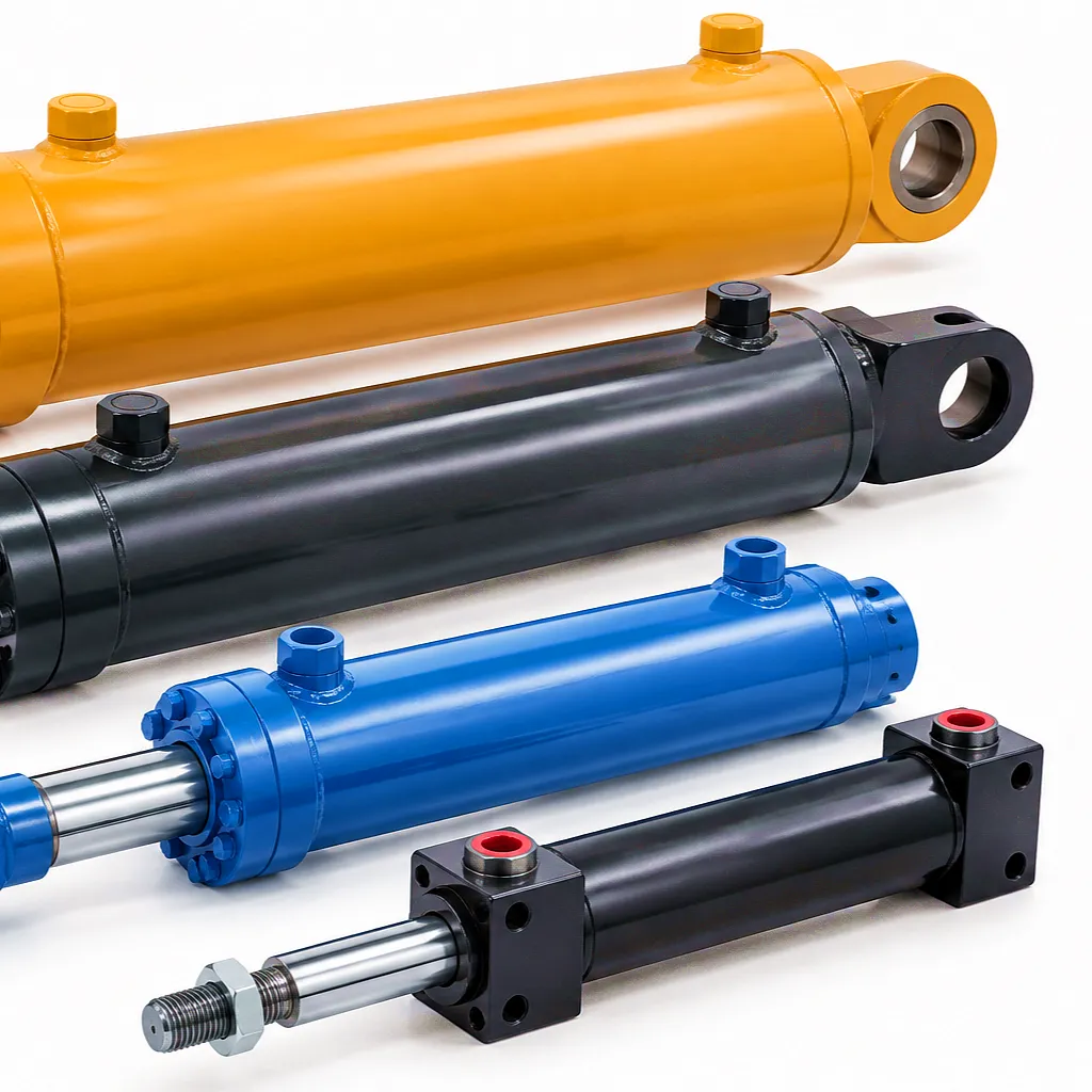
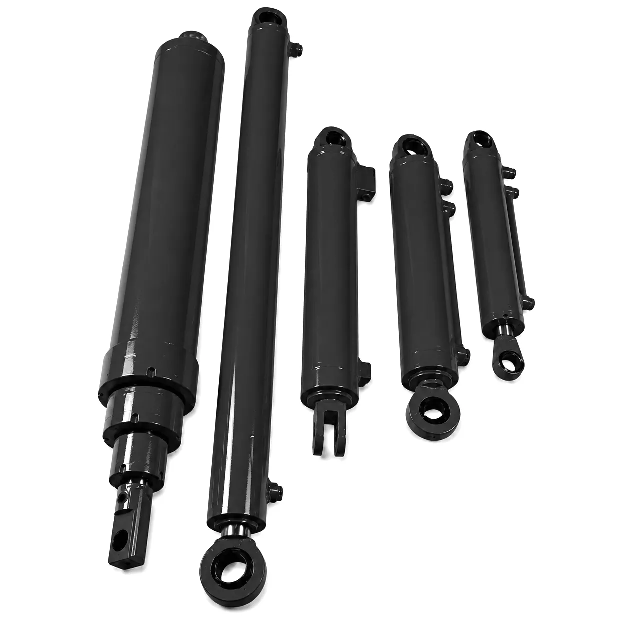
The hydraulic boom cylinder is one of engineering’s most versatile linear actuators. Across the UK’s industrial base — from automotive pressing in the Midlands to renewable energy installation off the Yorkshire coast — boom cylinders operate in conditions that span the full range of pressure, temperature, duty cycle, and contamination severity. Understanding which variant suits which application is what separates a cylinder that runs for a decade from one that demands frequent rebuilds.
Manufacturing Excellence
Ever Power: Precision Hydraulic Cylinder Manufacturing and Customisation
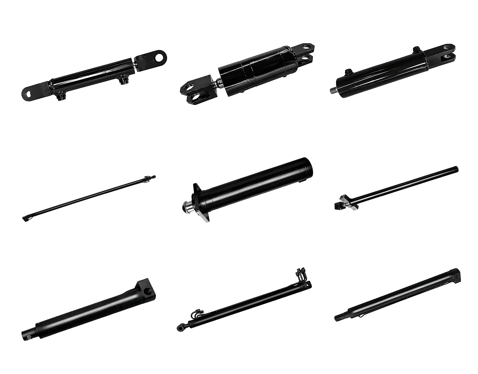
Ever Power operates a purpose-built hydraulic cylinder manufacturing facility equipped with CNC deep-boring machines capable of honing cylinder bores from 40 mm to 400 mm to a finish of Ra 0.2–0.4 µm. Hard chrome plating is conducted in-house under ISO 6158 controlled bath conditions, with plating thickness verified by eddy-current measurement on every rod before despatch. Each cylinder undergoes a hydrostatic proof test at 1.5x rated working pressure for a minimum of ten minutes, with results logged and supplied with the delivery documentation as standard for UK customer compliance.
The customisation capability at Ever Power spans the full design envelope — from accepting customer CAD drawings to reverse-engineering worn cylinders from dimensional measurements alone, a service regularly used by UK plant engineers who need replacements for machines where the original manufacturer no longer holds tooling. Minimum order quantities start at one piece for custom cylinders, with standard production lead times of 15–25 working days for custom designs and 5–10 working days for stocked standard configurations. Express air-freight and courier delivery to UK ports and warehouses is available for urgent breakdowns — a critical consideration for plant hire operators facing LOLER-triggered downtime penalties.
🔧 Custom Engineering
OEM drawings, CAD model exchange (STEP/IGES), reverse-engineering from worn samples. Unusual mounting configurations, non-standard port positions, and integrated valve bodies all accommodated in production.
📦 Supply Chain and Logistics
Пряме відправлення на адреси у Великій Британії через DHL, FedEx або морські контейнерні перевезення. Групові програми зберігання для дистриб'юторів з великими обсягами поставок у Великій Британії. Експортна документація, декларація CE та пакет для відстеження матеріалів включені.
📋 Гарантія якості
Система якості виробництва, що відповідає стандарту ISO 9001. Повна відстежуваність від плавки сировини до готового складання. Сертифікат гідростатичних випробувань, звіт про розміри, журнал товщини хрому та випробування на адгезію фарби постачаються стандартно з кожною партією.
Історія успіху клієнта: Sheffield Steel and Scrap Processors Ltd
Розташування тематичного дослідження
Шеффілд, Південний Йоркшир — переробка металобрухту та важка переробка
Компанія Sheffield Steel and Scrap Processors Ltd керує 12-акровим заводом з переробки матеріалів на східній околиці Шеффілда, де обробляють чорний та кольоровий брухт зі списаного промислового обладнання, кузовів транспортних засобів та сталевих конструкцій. Їхній основний кран-ножиця обробляє в середньому 380 тонн матеріалу за зміну, працюючи приблизно зі швидкістю 35 гідравлічних циклів за хвилину через два циліндри стріли — циліндр з ковпачком діаметром 160 мм та компенсаційний циліндр діаметром 100 мм — до 14 годин на день у періоди пікової навантаженості.
Наприкінці 2024 року обидва первинні циліндри стріли одночасно вийшли з ладу після 9800 годин роботи. Керівник інженерного відділу заводу, який працював лише з чотириденним періодом простою, зв'язався з Ever Power після онлайн-пошуку циліндрів стріли на замовлення з можливістю постачання до Великої Британії. Отримавши електронною поштою креслення з розмірами та робочі параметри, інженерна команда Ever Power підтвердила графік виробництва та план відвантаження протягом 24 годин. Замінні циліндри, виготовлені за оригінальними розмірами отвору виробника виробника, але модернізовані ущільненнями FKM та покриттям стрижня з карбіду вольфраму HVOF для роботи в умовах сильно забрудненого робочого середовища, були доставлені повітряним транспортом із заводу Ever Power та оформлені митницею Великої Британії протягом трьох робочих днів.
Встановлення та введення в експлуатацію зайняли ще один день. Кран повернувся до повної продуктивності на четвертий день, у межах початкового періоду зупинки. Станом на середину 2025 року обидва замінені циліндри накопичили 800 годин роботи без інцидентів, і під час першої планової перевірки не було виявлено жодних ознак корозії на поверхні штока, яка прискорила знос оригінальних циліндрів. Відтоді команда з Шеффілда уклала рамкову угоду з Ever Power, що охоплює два додаткові грейферні крани на об'єкті, з програмою планової заміни циліндрів, прив'язаною до контрольованих порогових значень годин роботи, а не до реактивних відмов.
Ключові показники проекту
Що кажуть клієнти з Великої Британії про циліндри стріли Ever Power
«Ми замінили циліндри стріли та маніпулятора на нашому Hitachi ZX350 за один період технічного обслуговування, використовуючи запасні частини Ever Power. Хромоване покриття штоків справді краще, ніж у оригінальних деталей, які ми знімали — жодної точкової корозивості через 600 годин, а ущільнення тримаються ідеально. Коли ви керуєте автопарком орендованого обладнання з Вулвергемптона з 40 машинами на об'єктах по всьому Вест-Мідлендсу, надійність циліндрів не є обговоренням. Терміни виконання робіт та якість документації ставить Ever Power вище за всіх інших постачальників, яких ми оцінювали».
— Алан К., менеджер з інженерії автопарку
Midlands Plant Hire Ltd, Вулвергемптон
«Циліндри стріли наших телескопічних навантажувачів мають індивідуальний хід, до якого ніхто інший не торкнувся б без 16-тижневого терміну виконання. Ever Power перетворила креслення на циліндри, що постачаються, за 18 робочих днів, з повним комплектом документів CE та сертифікатами гідростатичних випробувань, яких вимагає наша команда з безпеки на об'єкті. Регульована амортизація на торцевих кришках усунула брязкіт, який ми раніше чули при повному висуванні, що спричиняло втому кронштейнів. Чесно кажучи, це варте кожної копійки за подвійну ціну. Я б рекомендував їх будь-якому сільськогосподарському підряднику в Йоркширі, який працює з важким обладнанням».
— Сара Х., директор з операційної діяльності
Сільськогосподарські підрядники Дейлс, Гаррогейт, Північний Йоркшир
«За порадою інженерної команди Ever Power ми обрали стрижні з карбіду вольфраму HVOF та ущільнення з FKM для циліндрів кранів наших допоміжних суден у Північному морі. Вісімнадцять місяців потому, після безперервної експлуатації в одному з найагресивніших корозійних середовищ у світі, стрижні не демонструють жодної деградації поверхні, а ущільнення знаходяться в межах прийнятних параметрів витоку. Для менеджерів з морських закупівель, яким потрібно обґрунтувати вибір постачальника циліндрів перед технічним комітетом, документація щодо відстеження та сертифікати матеріалів від Ever Power – це саме те, що потрібно для процесу. Конкурентна ціна, серйозна технічна підтримка, і вони дійсно відповідають на дзвінки за абердинським часом».
— Девід М., менеджер із закупівель офшорного обладнання
North Atlantic Marine Services Ltd, Абердин
Часті запитання — Циліндри стріли у Великій Британії
Запитання, надіслані британськими інженерами, командами закупівель та керівниками заводів, які ставили своїми словами — так, як би ви сказали колезі або ввели в голосовий пошук.
Ever Power — прецизійні гідравлічні циліндри стріли
Готові знайти циліндр стріли для вашого проекту у Великій Британії?
Надсилайте ваші креслення, посилання на деталі OEM або деталі моделі машини безпосередньо нашій команді інженерів. Кошториси надсилаються протягом 24 годин. Документація CE та тестові пакети, що відповідають стандарту LOLER, входять до стандартної комплектації.
Отримайте цінову пропозицію зараз — [email protected]
Відповідь протягом 24 годин · Документація CE включена · Циліндри на замовлення від 1 штуки
редагування від gzl
 Ukrainian
  English
  Italian
  Portuguese
  Dutch
Dutch  Swedish
  Danish
  Finnish
  Polish
  Hindi
Hindi  Kazakh
  Turkish
  Romanian
  Spanish
  German
  Russian
  Korean
  Japanese
  Vietnamese
  Thai
Thai  Indonesian
  Malay
Malay  French
  Greek
Greek