
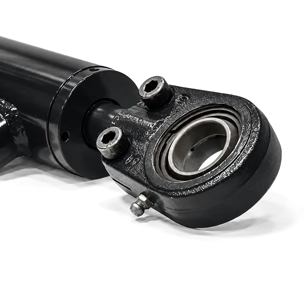
 When a hydraulic cylinder extends or retracts, it converts pressurised fluid energy into a precise linear mechanical force. That force — measured in kilonewtons (kN) or tonnes-force in many UK industrial contexts — is not a fixed value. It depends on three variables that every engineer must understand before specifying or replacing a cylinder: the working pressure of the hydraulic system, the effective cross-sectional area of the piston, and whether the cylinder is operating on its extend or retract stroke. Getting this calculation right is not merely an academic exercise. An undersized cylinder risks stall, structural stress, and premature seal failure; an oversized unit wastes capital expenditure and increases cycle times. Across manufacturing plants in Birmingham, construction sites in Manchester, and offshore installations in Aberdeen, correct force sizing is the difference between a reliable machine and a costly breakdown. This article explains the governing formula in plain terms, walks through worked examples covering common tonnage ranges, and shows you how to apply the same logic to your own hydraulic circuit.
The Hydraulic Cylinder Force Formula Explained
The fundamental relationship governing hydraulic cylinder output is deceptively simple: Force equals Pressure multiplied by Area. Written as a formula it reads F = P × A, where F is the output force in Newtons (N), P is the gauge pressure in Pascals (Pa), and A is the effective piston area in square metres (m²). Because real-world hydraulic systems use bar as the pressure unit and millimetres for bore diameter, it is almost always more convenient to work in those units directly. For an extend stroke, the effective area is the full bore area of the piston: A = π × (D/2)², where D is the bore diameter in millimetres. Converting to a usable result in kilonewtons, the working formula becomes F (kN) = P (bar) × A (mm²) × 0.1 / 1000, which simplifies to F (kN) = P × (π × D²/4) × 0.0001. On the retract stroke, the rod displaces part of the piston face, so the effective area drops to A_retract = π × ((D/2)² − (d/2)²), where d is the rod diameter. This annular area is always smaller, meaning the retract force is always lower than the extend force at the same pressure. British Standards BS EN ISO 3320 and BS EN ISO 10100 define the pressure and dimensional tolerances that underpin these calculations for hydraulic cylinders sold into UK markets, and any reputable supplier such as Ever Power designs to these benchmarks as standard.
Extend Stroke Force
F = P × π × (D/2)²
Full bore area applies. Maximum output stroke. D = bore diameter in mm, P = pressure in bar. Result in kN: multiply by 0.0001.
Retract Stroke Force
F = P × π × ((D/2)² − (d/2)²)
Annular area only. Rod diameter d reduces effective area. Retract force is always less than extend force at equal pressure.
Pressure Conversion
1 bar = 100,000 Pa = 14.5 psi
Most UK hydraulic systems express working pressure in bar. Standard mobile systems run 200–250 bar; industrial presses can reach 350–700 bar.
It is worth pausing on what “pressure” means in this context. The formula uses gauge pressure — pressure above atmospheric — not absolute pressure. If your circuit relief valve is set at 200 bar, that is the maximum gauge pressure the cylinder will see, and 200 bar is the number that goes into the formula. One common error in the field is confusing system pressure with pump output pressure after line losses; on long hydraulic runs, frictional losses of 5–15 bar are not unusual, so measured pressure at the cylinder port may be meaningfully lower than the pump outlet reading. Always measure or estimate pressure at the cylinder connection point for the most accurate force prediction.
Step-by-Step Worked Examples for Common UK Applications
Example 1 — Agricultural Bale Press (Lincolnshire Farm Equipment)
A round-bale press manufacturer in Lincolnshire needs to confirm that a cylinder with a 120 mm bore, 70 mm rod, and a system pressure of 180 bar generates enough force to compress straw to density. Extending: A = π × 60² = 11,310 mm². F_extend = 180 × 11,310 × 0.0001 = 203.6 kN (approximately 20.7 tonnes-force). Retracting: A_retract = π × (60² − 35²) = π × (3600 − 1225) = 7,461 mm². F_retract = 180 × 7,461 × 0.0001 = 134.3 kN. The 203 kN extend force exceeds the press requirement of 185 kN, so the specification is confirmed. This kind of sizing calculation is performed routinely by Ever Power’s engineering team before any cylinder leaves the factory, ensuring that each unit ships with its rated performance verified rather than assumed.
Example 2 — Excavator Boom Cylinder (Sheffield Steel Plant)
A Sheffield steelworks operates a material-handling excavator with a boom cylinder specification of 160 mm bore, 110 mm rod, and maximum operating pressure of 250 bar. Extend area: π × 80² = 20,106 mm². F_extend = 250 × 20,106 × 0.0001 = 502.6 kN — just over 51 tonnes-force. Retract area: π × (80² − 55²) = π × (6400 − 3025) = 10,602 mm². F_retract = 250 × 10,602 × 0.0001 = 265.1 kN. For a heavy machine working with scrap metal billets, the extend force of 502 kN is the critical figure. Note that the extend-to-retract ratio here is approximately 1.9:1 — a wide rod relative to bore, chosen deliberately to handle side-loading from the angled boom geometry. Selecting the right rod-to-bore ratio for your specific loading condition is one area where experienced suppliers like Ever Power add measurable engineering value.
Example 3 — Hydraulic Press for Automotive Parts (Birmingham Tier-2 Supplier)
An automotive stamping facility near Birmingham runs a hydraulic press at 320 bar with a 200 mm bore cylinder. Extend area: π × 100² = 31,416 mm². F_extend = 320 × 31,416 × 0.0001 = 1,005.3 kN — approximately 102 tonnes-force. At this force level, the press can form mild steel blanks up to 6 mm thick in a single stroke. The rod on this particular cylinder is 140 mm diameter, chosen to prevent buckling under the compressive load. Retract force: A_retract = π × (100² − 70²) = π × (10,000 − 4,900) = 16,022 mm². F_retract = 320 × 16,022 × 0.0001 = 512.7 kN. The retract stroke carries the die back to its start position and does not engage with the workpiece, so the lower retract force is entirely acceptable in this application. Understanding which stroke is the working stroke — and designing for that load case — is the first principle of hydraulic cylinder force engineering.
Five Variables That Determine Actual Cylinder Force Output
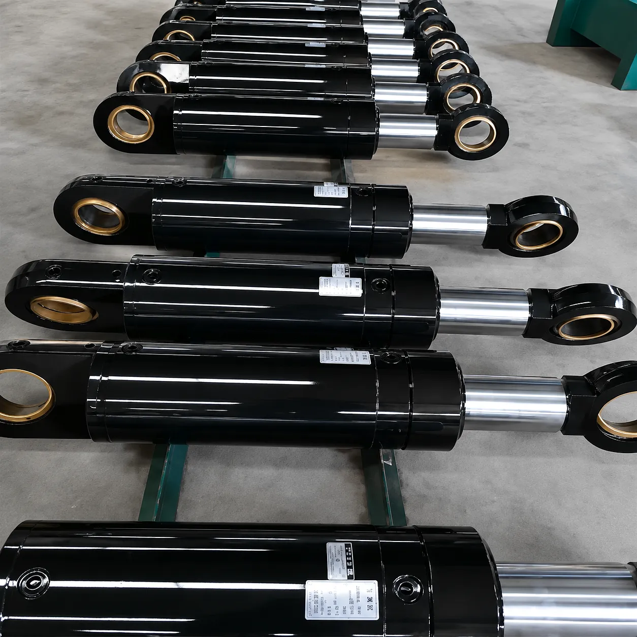
The formula gives a theoretical maximum, but the force a cylinder delivers in service can be reduced by several practical factors. Understanding each one protects against under-performance and accelerates troubleshooting when a machine is not delivering expected output.
System Working Pressure
The relief valve setting caps maximum force. Systems with worn pumps or poorly adjusted relief valves may deliver 20–40 bar below the nominal setting, directly reducing force output. Always verify system pressure at the cylinder port under load rather than reading the pump gauge only.
Bore Diameter Tolerances
Bore diameter directly determines piston area, and area appears as a squared term. A bore that is even 1 mm undersized on a 100 mm cylinder reduces the area by roughly 2%. For high-tonnage presses, this is commercially significant. Ever Power machines bores to H7 tolerance as standard, holding diameter to within ±0.015 mm on critical units.
Seal Friction Losses
Piston and rod seals generate a breakout friction force that the cylinder must overcome before it can do useful work. This is typically 3–7% of rated force on a new cylinder but can climb above 15% with aged or compressed seals. Low-friction PTFE-composite seals, as used in Ever Power’s precision range, keep this loss below 4% across the full operating temperature range of -20°C to +80°C.
Fluid Viscosity and Temperature
Cold hydraulic oil is thicker, increasing internal leakage past seals and reducing volumetric efficiency. In unheated UK factory environments during winter, oil starting at 5°C can behave quite differently from oil at the recommended 40–60°C operating temperature. A heated reservoir or warm-up cycle is recommended whenever ambient temperatures drop below 10°C.
Buckling Load Limit on the Rod
At long strokes or with slender rods, the rod itself can buckle under compressive load before the hydraulic pressure limit is reached. Euler’s column formula governs this and depends on rod diameter, stroke length, and end-fixing conditions. Exceeding the buckling load causes permanent rod damage. Ever Power engineers calculate the critical buckling load for every custom long-stroke order and may recommend increased rod diameter or a rear-cushioned design to keep the safety margin above 2.5:1.
Hydraulic Cylinder Technical and Performance Parameters
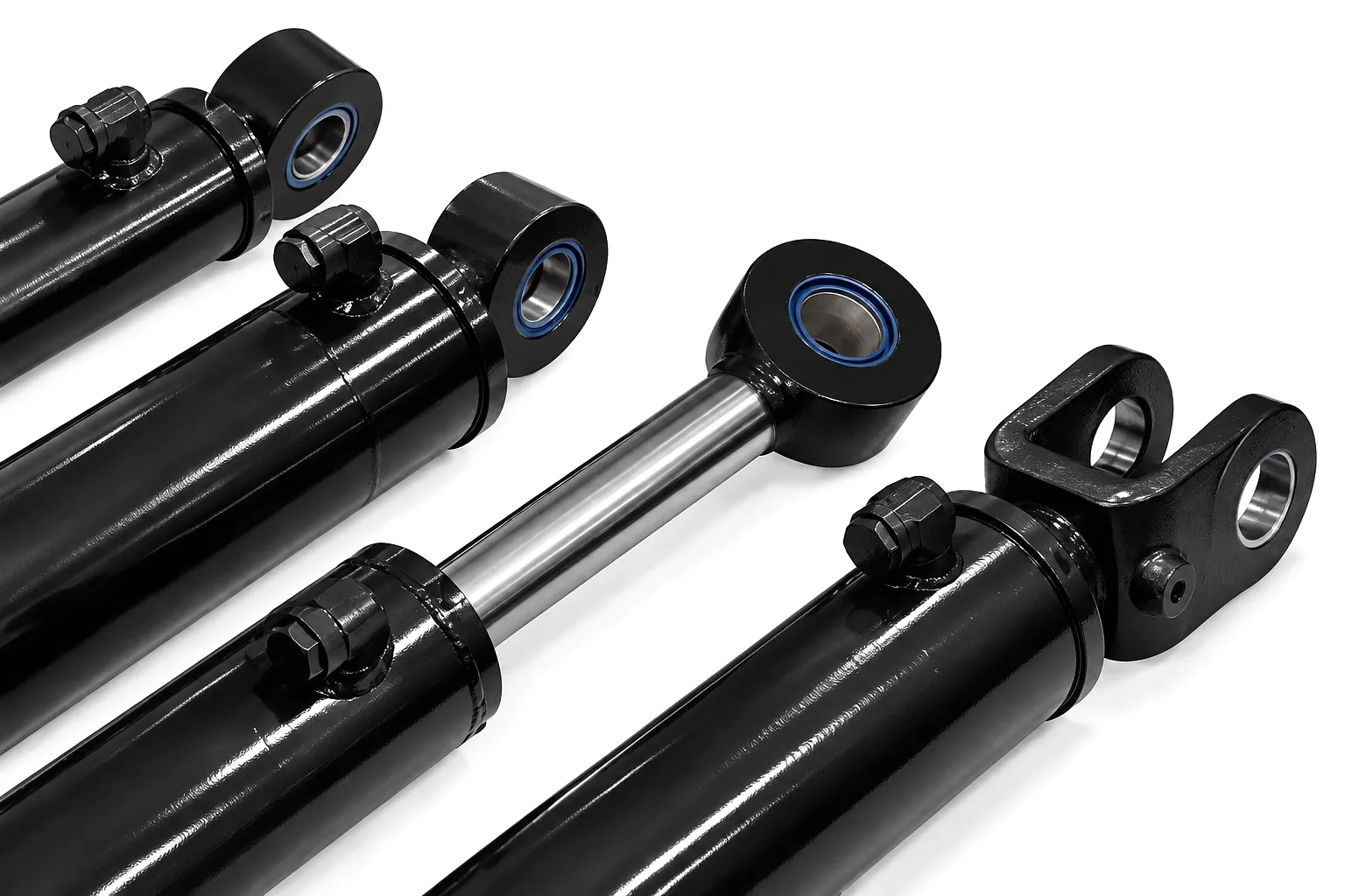
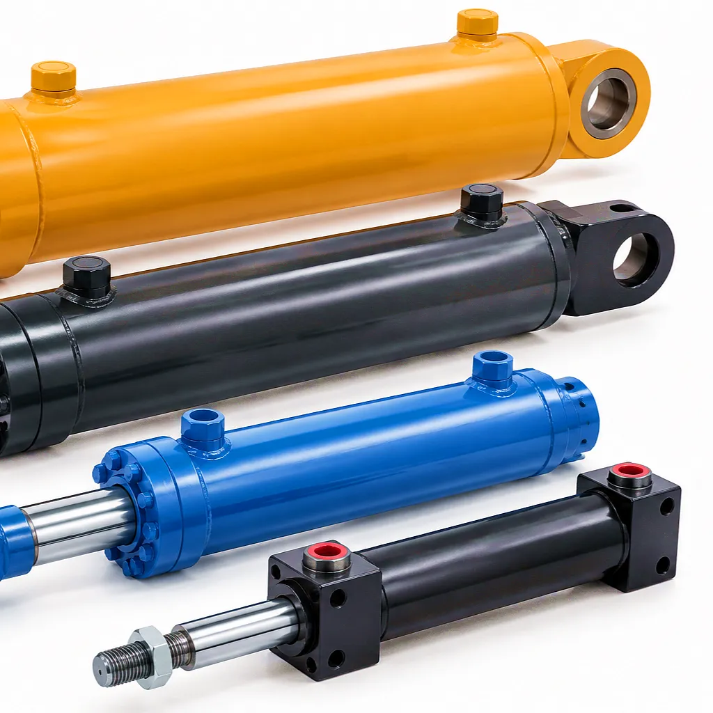
The table below covers the standard parameter ranges for industrial hydraulic cylinders as manufactured by Ever Power. Bore sizes, operating pressures, stroke lengths, and material choices are all configurable within these bounds. For applications outside standard ranges — such as ultra-high-pressure forming presses or deep-sea rated cylinders — Ever Power’s engineering team will prepare a custom specification upon request.
| Параметр | Стандартний діапазон | Extended / Custom Range | Нотатки |
|---|---|---|---|
| Діаметр отвору | 40 – 320 mm | Up to 800 mm | H7 tolerance standard; H6 available on precision grade |
| Rod Diameter | 22 – 250 mm | Up to 500 mm | f7 tolerance; hard chrome plated, 25–35 µm chrome depth |
| Робочий тиск | Up to 350 bar | Up to 700 bar | Test pressure = 1.5× working pressure per BS EN ISO 10100 |
| Довжина ходу | 50 – 3,000 mm | Up to 8,000 mm | Buckling check required above 2,000 mm; stage telescopic available |
| Extend Force (max) | Up to 2,800 kN | Up to 12,000 kN | Based on 700 bar × 800 mm bore combination; multi-stage press |
| Cylinder Tube Material | E355 Cold-drawn DOM Steel | Stainless 316L / Duplex S2205 | Inner surface honed to Ra 0.2–0.4 µm |
| Матеріал стрижня | 42CrMo4 / C45E | Induction hardened, HVOF-coated | Surface hardness 60–64 HRC on chrome layer |
| Seal Type | Polyurethane / NBR | PTFE composite / Viton (FKM) | FKM suits phosphate ester and high-temp applications |
| Робоча температура | від -20°C до +80°C | -45°C to +150°C | Low-temp grade uses special lip seal compound |
| Cushioning | Fixed / adjustable needle | Hydraulic deceleration valve | Reduces end-of-stroke impact loads; extends service life |
| Mounting Styles | Flange, Trunnion, Foot, Clevis | Spherical bearing, custom flange | Per ISO 6020/6022; custom bolt patterns available |
Working Principle and Core Material Selection
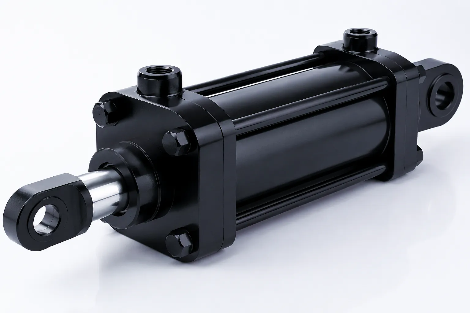
A double-acting hydraulic cylinder consists of a closed steel tube, a ground and chrome-plated rod attached to a piston, a gland seal assembly at the rod end, and inlet/outlet ports for hydraulic fluid. Pressurised oil enters the cap end port, bears against the full face of the piston, and drives the rod outward. When the directional control valve shifts, oil is directed to the rod-end port, acts against the smaller annular face, and pulls the rod back. Trapped oil on the opposite side vents back to the reservoir through the return line. The entire power conversion takes place without rotating parts, which is why hydraulic cylinders can generate forces far exceeding what electric motors of comparable size can produce — a 160 mm bore cylinder at 250 bar delivers the equivalent of a 15 kW electric drive at roughly one-tenth the package volume.
Material selection determines service life and reliability far more than geometry alone. The barrel tube must withstand internal burst pressure and hoop stress; Ever Power uses E355 cold-drawn seamless DOM steel as standard, which offers a minimum yield strength of 355 MPa and excellent weldability. For corrosive offshore or marine environments, 316L stainless steel or duplex grade S2205 (yield strength 450 MPa, superior chloride resistance) are specified. The piston rod carries both tensile pull and compressive push loads while sliding through the rod seal under continuous lubrication; 42CrMo4 alloy steel, quenched and tempered to 950–1100 MPa tensile strength, then hard chrome plated to a surface hardness of 60–64 HRC, forms the backbone of every standard rod. The 25–35 µm chrome layer provides corrosion resistance and a near-perfect sliding surface that minimises seal wear over millions of operating cycles.
Material Comparison
E355 DOM Steel
355 MPa yield — Standard duty
42CrMo4 Rod Steel
1,000+ MPa tensile — Rod standard
316L Stainless
Offshore / marine grade
Duplex S2205
450 MPa yield — Chloride-resistant
Industrial Application Scenarios Across the UK
The hydraulic cylinder force calculation discussed above applies across a wide spectrum of British industry. Each application places specific demands on bore size, pressure rating, mounting style, and environmental protection, and each has its own typical operating parameters worth knowing when specifying or sourcing replacement units.
Ever Power: Precision Manufacturing and Custom Cylinder Capability
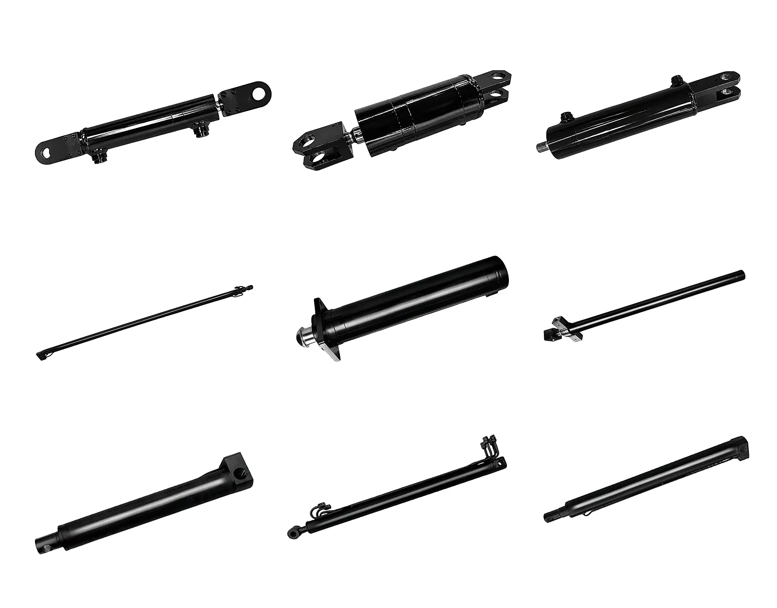
Ever Power operates a vertically integrated гідравлічний циліндр manufacturing facility with CNC deep-hole boring machines achieving bore diameters up to 800 mm, automated hard chrome plating lines, precision honing cells maintaining Ra 0.2 µm consistently, and a full hydraulic test bay where every cylinder is pressure-tested to 1.5× working pressure before despatch. The entire supply chain — steel tube, rod bar, seal kits, and end-cap forgings — is managed in-house, allowing Ever Power to guarantee lead times that consistently beat UK-based distributors relying on sub-contracted manufacturing.
🏭
Full Custom Bore & Stroke
Non-standard bore diameters, stroke lengths, port positions, and mounting flange patterns are all accommodated without tooling surcharges for orders of five or more units. CAD drawings supplied within 48 hours of enquiry.
🔧
Seal Kit Customisation
Ever Power’s seal engineering team matches seal compound to fluid type, temperature range, and cycling speed. NBR, polyurethane, PTFE-composite, Viton (FKM), and EPDM compounds are all held in stock. Bespoke seal kits can be despatched by next-day courier to UK addresses.
📋
Full Documentation Package
Every order ships with material certificates (EN 10204 3.1), dimensional inspection reports, pressure test certificates, and painting/surface treatment records. CE marking and UKCA marking documentation available for machinery directive compliance in the UK market.
🚢
Reliable UK Logistics
Standard units ship via consolidated sea freight with typical 18–25 day transit. Urgent replacement cylinders can be sent air freight to any UK airport, with same-day collection available at Heathrow, Gatwick, Manchester, and Birmingham freight terminals. DDP Incoterms quoted on request.
Tell us your bore, pressure, stroke, and application — we’ll handle the rest.
Історія успіху клієнта: підприємство з переробки металу у Вулвергемптоні
BrightMetal Recycling Ltd — Вулвергемптон, Вест-Мідлендс
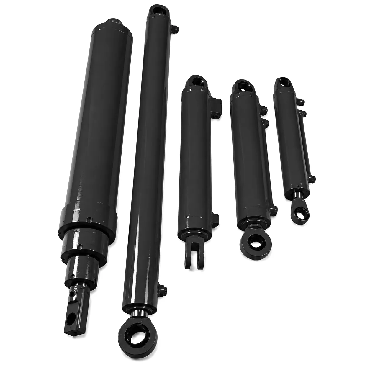 Компанія BrightMetal Recycling Ltd керує одним з найбільших підприємств з подрібнення та пакетування металобрухту у Вест-Мідлендсі, переробляючи приблизно 1200 тонн чорного та кольорового брухту на тиждень. Їхній існуючий гідравлічний пакетувальний прес, 20-річний агрегат німецького виробництва, був оснащений оригінальними циліндрами з номіналом 200 бар / діаметром отвору 160 мм. До 2023 року прискорені виходи з ладу ущільнень та внутрішні витоки через байпас знижували вихідне зусилля преса нижче порогу 380 кН, необхідного для формування щільних металевих тюків, що призводило до бракованих вантажів та втрати доходів від торговців брухтом, які вимагали постійної щільності тюків.
Інженер заводу BrightMetal зв'язався з Ever Power, надавши креслення розмірів оригінального циліндра та історію несправностей. Технічна команда Ever Power рекомендувала збільшити діаметр циліндра зі 160 мм до 180 мм, зберігаючи той самий хід поршня та схему кріплення, та збільшити робочий тиск до 250 бар. Ця зміна збільшила теоретичне зусилля розтягування з 402 кН до 636 кН, забезпечуючи комфортний запас 67% порівняно з вимогами процесу в 380 кН. Циліндри були виготовлені з ущільненнями поршня з PTFE-композиту та ущільненнями штока з поліуретану, обраними за їх сумісність з біорозкладною гідравлічною рідиною, яку завод застосував для дотримання екологічних норм. Два блоки були виготовлені, випробувані та відправлені протягом 19 днів після підтвердження замовлення, прибувши на завод у Вулвергемптоні з запланованою доставкою на палетах.
Монтаж було завершено протягом одного вихідного дня. Протягом чотирьох місяців після введення в експлуатацію компанія BrightMetal не повідомила про жодні незаплановані гідравлічні зупинки преса. Щільність тюків зросла до стабільних 1,05 тонни на кубічний метр, що перевищує мінімальний рівень 0,95 т/м³, який вимагає їхній найбільший покупець. Менеджер з технічного обслуговування заводу підрахував, що модернізація дозволила скоротити витрати приблизно на 28 000 фунтів стерлінгів на рік, які раніше були пов'язані з заміною ущільнень та простоєм обладнання, — термін окупності витрат на закупівлю циліндрів становить менше трьох місяців.
Що кажуть наші клієнти
★★★★★
«Ми доглядали за тими оригінальними циліндрами два роки. Замінні циліндри Ever Power були встановлені одразу — та сама схема кріплення болтів, ті ж положення портів — і з того часу прес працює з повною номінальною силою. Пакет документації був саме тим, що вимагав наш аудит HSE».
— Д. Парсонс, керівник інженерного відділу заводу, BrightMetal Recycling Ltd, Вулвергемптон
★★★★★
«Ми експлуатуємо 400-тонний кувальний прес у Ротеремі та замовили циліндр Ever Power на 320 бар та діаметр отвору 250 мм. Команда провела повний аналіз вигину та запропонувала товстіший шток, який би відповідав нашому ході 2800 мм. Циліндр виконав понад 600 000 циклів без помітного зносу отвору. Виняткова якість за таку ціну».
— Т. Блеквелл, старший інженер-механік, Rotherham Precision Forgings Ltd
★★★★★
«Наші зернозбиральні комбайни працюють на одних із найбагатших на бруд полів у Лінкольнширі. Ущільнення скребків попереднього постачальника циліндрів дозволяли бруду забруднювати оливу протягом одного сезону. Конструкція потрійного ущільнення скребка Ever Power витримала два повні цикли збирання врожаю — понад 1400 годин роботи — без жодного випадку забруднення гідравлічної оливи. Їхня оперативність у реагуванні на наш запит щодо індивідуального отвору отвору також була винятковою».
— Дж. Хаммонд, директор з технічного обслуговування автопарку, Eastern Agri Services, Бостон, Лінкольншир
Часті запитання — Гідравлічний циліндр, сила та розміри (Велика Британія)
Готові визначити розмір та знайти свій циліндр?
Ever Power — прецизійні гідравлічні циліндри, виготовлені на замовлення за вашими специфікаціями
Надішліть нам інформацію про ваш діаметр отвору, тиск, хід, діаметр штока та застосування. Наші інженери розглянуть ваші вимоги та нададуть повну специфікацію та ціну протягом одного робочого дня.
Цю статтю підготувала команда технічного контенту компанії Ever Power. Усі розрахунки сил відповідають стандартам BS EN ISO 3320 та BS EN ISO 10100. З питань конкретних інженерних питань звертайтеся [email protected].
 Ukrainian
  English
  Italian
  Portuguese
  Dutch
Dutch  Swedish
  Danish
  Finnish
  Polish
  Hindi
Hindi  Kazakh
  Turkish
  Romanian
  Spanish
  German
  Russian
  Korean
  Japanese
  Vietnamese
  Thai
Thai  Indonesian
  Malay
Malay  French
  Greek
Greek